| Section |
Page |
| Dell™ XPS™ L701X Service Manual |
1 |
| Notes, Cautions, and Warnings |
2 |
| Contents |
3 |
| 1 |
9 |
| Before You Begin |
9 |
| Recommended Tools |
9 |
| Turning Off Your Computer |
9 |
| 1 Save and close all open files and exit all open programs. |
9 |
| 2 To shut down the operating system, click Start and then click Shut Down. |
9 |
| 3 Ensure that the computer is turned off. If your computer did not automatically turn off when you shut down the operating system, press and hold the power button until the computer turns off. |
9 |
| Before Working Inside Your Computer |
10 |
| 1 Ensure that the work surface is flat and clean to prevent the computer cover from being scratched. |
10 |
| 2 Turn off your computer (see \ |
10 |
| 3 Disconnect all telephone or network cables from the computer. |
10 |
| 4 Press and eject any installed cards from the Media Card Reader. |
10 |
| 5 Disconnect your computer and all attached devices from their electrical outlets. |
10 |
| 6 Disconnect all attached devices from your computer. |
11 |
| 7 Remove the battery (see \ |
11 |
| 8 Turn the computer top-side up, open the display, and press the power button to ground the system board. |
11 |
| 2 |
13 |
| Battery |
13 |
| Removing the Battery |
13 |
| 1 Follow the instructions in \ |
13 |
| 2 Turn the computer over. |
13 |
| 3 Slide the battery release latch to the side. |
13 |
| 4 Lift the battery up at an angle and remove it from the battery bay. |
13 |
| Replacing the Battery |
14 |
| 1 Follow the instructions in \ |
14 |
| 2 Align the tabs on the battery with the slots in the battery bay and press the battery down until it clicks into place. |
14 |
| 3 |
15 |
| Module Cover |
15 |
| Removing the Module Cover |
15 |
| 1 Follow the instructions in \ |
15 |
| 2 Remove the battery (see \ |
15 |
| 3 Loosen the captive screw that secures the module cover to the base cover. |
15 |
| 4 Use your fingertips to release the tabs on the module cover from the slots on the base cover and lift it off the base cover. |
15 |
| Replacing the Module Cover |
16 |
| 1 Follow the instructions in \ |
16 |
| 2 Align the tabs on the module cover with the slots on the base cover and snap the module cover into place. |
16 |
| 3 Tighten the captive screw that secures the module cover to the base cover. |
16 |
| 4 Replace the battery (see \ |
16 |
| 4 |
17 |
| Memory Module(s) |
17 |
| Removing the Memory Module(s) |
17 |
| 1 Follow the instructions in \ |
17 |
| 2 Remove the battery (see \ |
17 |
| 3 Remove the module cover (see \ |
17 |
| 4 Use your fingertips to carefully spread apart the securing clips on each end of the memory-module connector until the memory module pops up. |
17 |
| 5 Remove the memory module from the memory-module connector. |
18 |
| Replacing the Memory Module(s) |
18 |
| 1 Follow the instructions in \ |
18 |
| 2 Align the notch in the memory module with the tab in the memory-module connector. |
19 |
| 3 Slide the memory module firmly into the memory-module connector at a 45-degree angle, and press the memory module down until it clicks into place. If you do not hear the click, remove the memory module and reinstall it. |
19 |
| 4 Replace the module cover (see \ |
20 |
| 5 Replace the battery (see \ |
20 |
| 6 Connect the AC adapter to your computer and an electrical outlet. |
20 |
| 7 Turn on the computer. |
20 |
| 5 |
21 |
| Wireless Mini-Card(s) |
21 |
| Removing the Mini-Card(s) |
21 |
| 1 Follow the instructions in \ |
21 |
| 2 Remove the battery (see \ |
21 |
| 3 Remove the module cover (see \ |
21 |
| 4 Remove the memory module(s) (see \ |
22 |
| 5 Follow the instructions in step 5 in \ |
22 |
| 6 Remove the optical drive (see \ |
22 |
| 7 Remove the palm-rest assembly (see \ |
22 |
| 8 Remove the keyboard (see \ |
22 |
| 9 Disconnect the antenna cables from the Mini-Card(s). |
22 |
| 10 Remove the screw that secures the Mini-Card to the system board. |
22 |
| 11 Lift the Mini-Card(s) out of the system-board connector. |
23 |
| Replacing the Mini-Card(s) |
23 |
| 1 Follow the instructions in \ |
23 |
| 2 Remove the new Mini-Card from its packaging. |
23 |
| 3 Insert the Mini-Card connector at a 45-degree angle into the system-board connector. |
24 |
| 4 Press the other end of the Mini-Card down into the slot on the system board and replace the screw that secures the Mini-Card to the system board. |
24 |
| 5 Connect the appropriate antenna cables to the Mini-Card(s) you are installing. The following table provides the antenna cable color scheme for the Mini-Cards supported by your computer. |
24 |
| 6 Replace the keyboard (see \ |
24 |
| 7 Replace the palm-rest assembly (see \ |
24 |
| 8 Replace the optical drive (see \ |
24 |
| 9 Follow the instructions in step 5 in \ |
24 |
| 10 Replace the memory module(s) (see \ |
24 |
| 11 Replace the module cover (see \ |
24 |
| 12 Replace the battery (see \ |
24 |
| 13 Install the drivers and utilities for your computer, as required. |
25 |
| 6 |
27 |
| Hard Drive(s) |
27 |
| Removing the Hard Drive(s) |
27 |
| 1 Follow the instructions in \ |
27 |
| 2 Remove the battery (see \ |
27 |
| 3 Remove the module cover (see \ |
27 |
| 4 Remove the memory module(s) (see \ |
28 |
| 5 Remove hard drive 1 and/or hard drive 2 from the computer base: |
28 |
| 6 Remove the four screws that secure the hard-drive bracket to the hard drive. |
29 |
| 7 Lift the hard-drive bracket off the hard drive. |
29 |
| Replacing the Hard Drive(s) |
30 |
| 1 Follow the instructions in \ |
30 |
| 2 Remove the new hard drive from its packaging. |
30 |
| 3 Place the hard-drive bracket on the hard drive. |
30 |
| 4 Replace the four screws that secure the hard-drive bracket to the hard drive. |
30 |
| 5 Replace hard drive 1 and/or hard drive 2 in the computer base: |
30 |
| 6 Replace the memory module(s) (see \ |
30 |
| 7 Replace the module cover (see \ |
31 |
| 8 Replace the battery (see \ |
31 |
| 7 |
33 |
| Optical Drive |
33 |
| Removing the Optical Drive |
33 |
| 1 Follow the instructions in \ |
33 |
| 2 Remove the battery (see \ |
33 |
| 3 Remove the module cover (see \ |
33 |
| 4 Remove the memory module(s) (see \ |
33 |
| 5 Remove the screw that secures the optical drive to the base cover. |
33 |
| 6 Slide the optical drive out of the optical-drive bay. |
33 |
| Replacing the Optical Drive |
34 |
| 1 Follow the instructions in \ |
34 |
| 2 Slide the optical drive into the optical-drive bay until it is fully seated. |
34 |
| 3 Replace the screw that secures the optical drive to the base cover. |
34 |
| 4 Replace the memory module(s) (see \ |
34 |
| 5 Replace the module cover (see \ |
34 |
| 6 Replace the battery (see \ |
34 |
| 8 |
37 |
| Palm-Rest Assembly |
37 |
| Removing the Palm-Rest Assembly |
37 |
| 1 Follow the instructions in \ |
37 |
| 2 Remove the battery (see \ |
37 |
| 3 Remove the module cover (see \ |
37 |
| 4 Remove the memory module(s) (see \ |
37 |
| 5 Follow the instructions in step 5 in \ |
37 |
| 6 Remove the optical drive (see \ |
37 |
| 7 Remove the three screws that secure the palm-rest assembly to the base cover. |
37 |
| 8 Turn the computer over and open the display as far as possible. |
38 |
| 9 Using your fingertip, gently push the tab to release the palm-rest assembly from the top cover. |
38 |
| 10 Using your fingertips, gently ease the palm-rest assembly from the top cover. |
39 |
| 11 Without pulling hard on the palm-rest assembly, turn the palm-rest assembly over and place it on the top cover. |
39 |
| 12 Lift the connector latch and pull the pull-tab to disconnect the control-strip cable from the system-board connector. |
39 |
| 13 Lift the connector latch and pull the pull-tab to disconnect the touch-pad cable from the system-board connector. |
39 |
| 14 Lift the palm-rest assembly off the top cover. |
39 |
| Replacing the Palm-Rest Assembly |
40 |
| 1 Follow the instructions in \ |
40 |
| 2 Slide the touch-pad cable into the system-board connector and press down on the connector latch to secure the cable. |
40 |
| 3 Slide the control-strip cable into the system-board connector and press down on the connector latch to secure the cable. |
40 |
| 4 Place the palm-rest assembly on the top cover and gently snap the palm-rest assembly into place. |
40 |
| 5 Close the display and turn the computer over. |
40 |
| 6 Replace the three screws that secure the palm-rest assembly to the base cover. |
40 |
| 7 Replace the optical drive (see \ |
40 |
| 8 Follow the instructions in step 5 in \ |
41 |
| 9 Replace the memory module(s) (see \ |
41 |
| 10 Replace the module cover (see \ |
41 |
| 11 Replace the battery (see \ |
41 |
| 9 |
43 |
| Keyboard |
43 |
| Removing the Keyboard |
43 |
| 1 Follow the instructions in \ |
43 |
| 2 Remove the battery (see \ |
43 |
| 3 Remove the module cover (see \ |
43 |
| 4 Remove the memory module(s) (see \ |
43 |
| 5 Follow the instructions in step 5 in \ |
43 |
| 6 Remove the optical drive (see \ |
43 |
| 7 Remove the palm-rest assembly (see \ |
43 |
| 8 Remove the four screws that secure the keyboard to the top cover. |
43 |
| 9 Without pulling hard on the keyboard, carefully lift the keyboard and slide the keyboard tabs out of the slots on the top cover. |
43 |
| 10 Turn the keyboard over and place it on the top cover. |
44 |
| 11 Lift the connector latch and pull the pull-tab to disconnect the keyboard backlight cable from the system-board connector. |
44 |
| 12 Lift the connector latch and pull the pull-tab to disconnect the keyboard cable from the system-board connector. |
44 |
| 13 Lift the keyboard off the top cover. |
45 |
| Replacing the Keyboard |
45 |
| 1 Follow the instructions in \ |
45 |
| 2 Slide the keyboard cable into the system-board connector and press down on the connector latch to secure the cable. |
45 |
| 3 Slide the keyboard backlight cable into the system-board connector and press down on the connector latch to secure the cable. |
45 |
| 4 Slide the tabs on the keyboard into the slots on the top cover and lower the keyboard into place. |
45 |
| 5 Replace the four screws that secure the keyboard to the top cover. |
45 |
| 6 Replace the palm-rest assembly (see \ |
46 |
| 7 Replace the optical drive (see \ |
46 |
| 8 Follow the instructions in step 5 in \ |
46 |
| 9 Replace the memory module(s) (see \ |
46 |
| 10 Replace the module cover (see \ |
46 |
| 11 Replace the battery (see \ |
46 |
| 10 |
47 |
| Power-Button Board |
47 |
| Removing the Power-Button Board |
47 |
| 1 Follow the instructions in \ |
47 |
| 2 Remove the battery (see \ |
47 |
| 3 Remove the module cover (see \ |
47 |
| 4 Remove the memory module(s) (see \ |
47 |
| 5 Follow the instructions in step 5 in \ |
47 |
| 6 Remove the optical drive (see \ |
47 |
| 7 Remove the palm-rest assembly (see \ |
47 |
| 8 Turn the palm-rest assembly over. |
47 |
| 9 Lift the connector latch and pull the pull-tab to disconnect the power-button board cable from the connector on the power-button board. |
47 |
| 10 Remove the two screws that secure the power-button board to the palm-rest assembly. |
48 |
| 11 Lift the power-button board off the palm-rest assembly. |
48 |
| Replacing the Power-Button Board |
48 |
| 1 Follow the instructions in \ |
48 |
| 2 Use the alignment post to place the power-button board on the palm-rest assembly. |
48 |
| 3 Replace the two screws that secure the power-button board to the palm-rest assembly. |
48 |
| 4 Slide the power-button board cable into the connector on the power-button board and press down on the connector latch to secure the cable. |
48 |
| 5 Replace the palm-rest assembly (see \ |
48 |
| 6 Replace the optical drive (see \ |
48 |
| 7 Follow the instructions in step 5 in \ |
49 |
| 8 Replace the memory module(s) (see \ |
49 |
| 9 Replace the module cover (see \ |
49 |
| 10 Replace the battery (see \ |
49 |
| 11 |
51 |
| Coin-Cell Battery |
51 |
| Removing the Coin-Cell Battery |
51 |
| 1 Follow the instructions in \ |
51 |
| 2 Remove the battery (see \ |
51 |
| 3 Remove the module cover (see \ |
51 |
| 4 Remove the memory module(s) (see \ |
51 |
| 5 Follow the instructions in step 5 in \ |
51 |
| 6 Remove the optical drive (see \ |
51 |
| 7 Remove the palm-rest assembly (see \ |
51 |
| 8 Using a plastic scribe, gently pry the coin-cell out of the battery socket on the system board. |
51 |
| Replacing the Coin-Cell Battery |
52 |
| 1 Follow the instructions in \ |
52 |
| 2 With the positive side facing up, snap the coin-cell battery into the battery socket on the system board. |
52 |
| 3 Replace the palm-rest assembly (see \ |
52 |
| 4 Replace the optical drive (see \ |
52 |
| 5 Follow the instructions in step 5 in \ |
52 |
| 6 Replace the memory module(s) (see \ |
52 |
| 7 Replace the module cover (see \ |
52 |
| 8 Replace the battery (see \ |
52 |
| 12 |
55 |
| Internal Card With Bluetooth® Wireless Technology |
55 |
| Removing the Bluetooth Card |
55 |
| 1 Follow the instructions in \ |
55 |
| 2 Remove the battery (see \ |
55 |
| 3 Remove the module cover (see \ |
55 |
| 4 Remove the memory module(s) (see \ |
55 |
| 5 Follow the instructions in step 5 in \ |
55 |
| 6 Remove the optical drive (see \ |
55 |
| 7 Remove the palm-rest assembly (see \ |
55 |
| 8 Disconnect the Bluetooth-card cable from the system-board connector. |
55 |
| 9 Lift the Bluetooth card along with the cable off the computer base. |
55 |
| Replacing the Bluetooth Card |
56 |
| 1 Follow the instructions in \ |
56 |
| 2 Slide the Bluetooth card into the slot on the computer base and secure it in place. |
56 |
| 3 Connect the Bluetooth-card cable to the system-board connector. |
56 |
| 4 Replace the palm-rest assembly (see \ |
56 |
| 5 Replace the optical drive (see \ |
56 |
| 6 Follow the instructions in step 5 in \ |
56 |
| 7 Replace the memory module(s) (see \ |
56 |
| 8 Replace the module cover (see \ |
56 |
| 9 Replace the battery (see \ |
57 |
| 13 |
59 |
| Display |
59 |
| Display Assembly |
59 |
| Removing the Display Assembly |
59 |
| 1 Follow the instructions in \ |
59 |
| 2 Remove the battery (see \ |
59 |
| 3 Remove the module cover (see \ |
59 |
| 4 Remove the memory module(s) (see \ |
59 |
| 5 Follow the instructions in step 5 in \ |
59 |
| 6 Remove the two screws that secure the display assembly to the base cover. |
59 |
| 7 Remove the optical drive (see \ |
60 |
| 8 Remove the palm-rest assembly (see \ |
60 |
| 9 Disconnect the antenna cables from the Mini-Card(s). |
60 |
| 10 Turn the computer over and open the display as far as possible. |
60 |
| 11 Note the routing of the Mini-Card antenna cables and remove the cables from the routing guides. |
60 |
| 12 Remove the keyboard (see \ |
60 |
| 13 Pull the pull-tab to disconnect the touch-screen cable from the system-board connector. |
60 |
| 14 Remove the screw that secures the display grounding cable to the top cover. |
60 |
| 15 Pull the pull-tab to disconnect the display cable from the system-board connector. |
61 |
| 16 Note the routing of the display cable and remove the cable from the routing guides. |
61 |
| 17 Remove the four screws that secure the display assembly to the top cover. |
61 |
| 18 Lift the display assembly off the computer base. |
61 |
| Replacing the Display Assembly |
62 |
| 1 Follow the instructions in \ |
62 |
| 2 Place the display assembly in position and replace the four screws that secure the display assembly to the top cover. |
62 |
| 3 Route the display cable through the routing guides. |
62 |
| 4 Connect the display cable to the system-board connector. |
62 |
| 5 Replace the screw that secures the display grounding cable to the top cover. |
62 |
| 6 Connect the touch screen cable to the system-board connector. |
62 |
| 7 Route the Mini-Card antenna cables through the routing guides. |
62 |
| 8 Connect the appropriate antenna cables to the Mini-Cards(s) on your computer (see \ |
63 |
| 9 Replace the keyboard (see \ |
63 |
| 10 Replace the palm-rest assembly (see \ |
63 |
| 11 Replace the optical drive (see \ |
63 |
| 12 Replace the two screws that secure the display assembly to the base cover. |
63 |
| 13 Follow the instructions in step 5 in \ |
63 |
| 14 Replace the memory module(s) (see \ |
63 |
| 15 Replace the module cover (see \ |
63 |
| 16 Replace the battery (see \ |
63 |
| Display Bezel |
63 |
| Removing the Display Bezel |
63 |
| 1 Follow the instructions in \ |
63 |
| 2 Remove the display assembly (see \ |
63 |
| 3 Push the display bezel outwards to release it from the tabs that secure the display bezel to the back cover. |
63 |
| 4 Using your fingertips gently pry the outside edge of the display bezel off the back cover. |
63 |
| 5 Lift the display bezel off the display assembly. |
63 |
| Replacing the Display Bezel |
64 |
| 1 Follow the instructions in \ |
64 |
| 2 Align the display bezel with the display back cover, and gently snap it into place. |
64 |
| 3 Replace the display assembly (see \ |
64 |
| Display Panel |
64 |
| Removing the Display Panel |
64 |
| 1 Follow the instructions in \ |
64 |
| 2 Remove the display assembly (see \ |
65 |
| 3 Remove the display bezel (see \ |
65 |
| 4 Remove the camera module (see \ |
65 |
| 5 Pull the pull-tab to disconnect the touch-screen board cable from the connector on the touch-screen board. |
65 |
| 6 Remove the 12 screws that secure the display panel to the display back cover. |
65 |
| 7 Note the routing of the antenna cables and remove them from the routing guide on the right display hinge. |
65 |
| 8 Note the routing of the display cable and remove it from the routing guide on the left display hinge. |
65 |
| 9 Lift the display panel off the display back cover. |
66 |
| Replacing the Display Panel |
66 |
| 1 Follow the instructions in \ |
66 |
| 2 Place the display panel over the display back cover. |
66 |
| 3 Route the display cable through the routing guide on the left display hinge. |
66 |
| 4 Route the antenna cables through the routing guide on the right display hinge. |
66 |
| 5 Use the alignment posts to place the touch-screen board on the display back cover. |
66 |
| 6 Connect the touch-screen board cable to the connector on the touch-screen board. |
67 |
| 7 Replace the 12 screws that secure the display panel to the display back cover. |
67 |
| 8 Replace the camera module (see \ |
67 |
| 9 Replace the display bezel (see \ |
67 |
| 10 Replace the display assembly (see \ |
67 |
| Display Cable |
67 |
| Removing the Display Cable |
67 |
| 1 Follow the instructions in \ |
67 |
| 2 Remove the display assembly (see \ |
67 |
| 3 Remove the display bezel (see \ |
67 |
| 4 Remove the camera module (\ |
67 |
| 5 Remove the display panel (see \ |
67 |
| 6 Turn the display panel over and place it on a clean surface. |
67 |
| 7 Pull the pull-tab to disconnect the display cable from the connector on the display panel. |
67 |
| 8 Gently peel off the display cable from the display panel. |
68 |
| Replacing the Display Cable |
68 |
| 1 Follow the instructions in \ |
68 |
| 2 Adhere the display cable along the edge of the display panel. |
68 |
| 3 Connect the display cable to the connector on the display panel. |
68 |
| 4 Replace the display panel (see \ |
68 |
| 5 Replace the camera module (see \ |
68 |
| 6 Replace the display bezel (see \ |
69 |
| 7 Replace the display assembly (\ |
69 |
| Display-Panel Brackets |
69 |
| Removing the Display-Panel Brackets |
69 |
| 1 Follow the instructions in \ |
69 |
| 2 Remove the display assembly (see \ |
69 |
| 3 Remove the display bezel (see \ |
69 |
| 4 Remove the camera module (\ |
69 |
| 5 Remove the display panel (see \ |
69 |
| 6 Remove the eight screws (four on each side) that secure the display-panel brackets to the display panel. |
69 |
| 7 Remove the display-panel brackets off the display panel. |
69 |
| Replacing the Display-Panel Brackets |
70 |
| 1 Follow the instructions in \ |
70 |
| 2 Place the display-panel brackets in position. |
70 |
| 3 Replace the eight screws (four on each side) that secure the display-panel brackets to the display panel. |
70 |
| 4 Replace the display panel (see \ |
70 |
| 5 Replace the camera module (see \ |
70 |
| 6 Replace the display bezel (see \ |
70 |
| 7 Replace the display assembly (\ |
70 |
| Camera Module |
73 |
| Removing the Camera Module |
73 |
| Replacing the Camera Module |
76 |
| 15 |
79 |
| Top Cover |
79 |
| Removing the Top Cover |
79 |
| 1 Follow the instructions in \ |
79 |
| 2 Press and eject any installed cards from the Media Card Reader. |
79 |
| 3 Remove the battery (see \ |
79 |
| 4 Remove the module cover (see \ |
79 |
| 5 Remove the memory module(s) (see \ |
79 |
| 6 Follow the instructions in step 5 in \ |
79 |
| 7 Remove the optical drive (see \ |
79 |
| 8 Remove the palm-rest assembly (see \ |
79 |
| 9 Remove the keyboard (see \ |
79 |
| 10 Remove the Mini-Card(s) (see \ |
79 |
| 11 Remove the bluetooth card (see \ |
80 |
| 12 Remove the display assembly (see \ |
80 |
| 13 Remove the ten screws that secure the top-cover assembly to the base cover. |
80 |
| 14 Turn the computer over. |
80 |
| 15 Remove the ten screws that secure the top-cover assembly to the base cover. |
80 |
| 16 Disconnect the subwoofer cable from the system-board connector. |
81 |
| 17 Using your fingertips, gently ease the top-cover assembly from the base cover. |
82 |
| 18 Lift the top cover assembly off the base cover. |
82 |
| 19 Remove the AC-adapter connector (see \ |
83 |
| 20 Remove the USB board (see \ |
83 |
| 21 Remove the fan (see \ |
83 |
| 22 Remove the heat sink (see \ |
83 |
| 23 Remove the processor module (see \ |
83 |
| 24 Remove the I/O board (see \ |
83 |
| 25 Remove the TV antenna connector (see \ |
83 |
| 26 Remove the system board (see \ |
83 |
| 27 Remove the speakers (see \ |
83 |
| Replacing the Top Cover |
84 |
| 1 Follow the instructions in \ |
84 |
| 2 Replace the speakers (see \ |
84 |
| 3 Replace the system board (see \ |
84 |
| 4 Replace the TV antenna connector (see \ |
84 |
| 5 Replace the I/O board (see \ |
84 |
| 6 Replace the processor module (see \ |
84 |
| 7 Replace the heat sink (see \ |
84 |
| 8 Replace the fan (see \ |
84 |
| 9 Replace the AC-adapter connector (see \ |
84 |
| 10 Replace the USB board (see \ |
84 |
| 11 Route the subwoofer cable through the slot on the top cover. |
84 |
| 12 Connect the subwoofer cable to the system-board connector. |
84 |
| 13 Align the tabs on the top cover with the slots on the base cover and snap the top-cover assembly onto the base cover. |
84 |
| 14 Replace the ten screws that secure the top-cover assembly to the base cover. |
84 |
| 15 Turn the computer over and replace the ten screws that secure the top-cover assembly to the base cover. |
84 |
| 16 Replace the Bluetooth-card (see \ |
84 |
| 17 Replace the Mini-Card(s) (see \ |
84 |
| 18 Replace the display assembly (see \ |
84 |
| 19 Replace the keyboard (see \ |
84 |
| 20 Replace the palm-rest assembly (see \ |
84 |
| 21 Replace the optical drive (see \ |
84 |
| 22 Follow the instructions in step 5 in \ |
85 |
| 23 Replace the memory module(s) (see \ |
85 |
| 24 Replace the module cover (see \ |
85 |
| 25 Replace any blank or card you removed from the Media Card Reader slot. |
85 |
| 26 Replace the battery (see \ |
85 |
| 16 |
87 |
| Subwoofer |
87 |
| Removing the Subwoofer |
87 |
| 1 Follow the instructions in \ |
87 |
| 2 Remove the battery (see \ |
87 |
| 3 Remove the module cover (see \ |
87 |
| 4 Remove the memory module(s) (see \ |
87 |
| 5 Follow the instructions in step 5 in \ |
87 |
| 6 Remove the optical drive (see \ |
87 |
| 7 Remove the palm-rest assembly (see \ |
87 |
| 8 Remove the keyboard (see \ |
87 |
| 9 Remove the display assembly (see \ |
87 |
| 10 Remove the Mini-Card(s) (see \ |
87 |
| 11 Remove the bluetooth card (see \ |
88 |
| 12 Follow the instructions from step 13 to step 18 in \ |
88 |
| 13 Remove the four screws that secure the subwoofer to the base cover. |
88 |
| 14 Lift the subwoofer along with the cable off the base cover. |
88 |
| Replacing the Subwoofer |
88 |
| 1 Follow the instructions in \ |
88 |
| 2 Align the screw holes on the subwoofer with the screw holes on the base cover. |
88 |
| 3 Replace the four screws that secure the subwoofer to the base cover. |
88 |
| 4 Follow the instructions from step 11 to step 15 in \ |
89 |
| 5 Replace the bluetooth card (see \ |
89 |
| 6 Replace the Mini-Card(s) (see \ |
89 |
| 7 Replace the display assembly (see \ |
89 |
| 8 Replace the keyboard (see \ |
89 |
| 9 Replace the palm-rest assembly (see \ |
89 |
| 10 Replace the optical drive (see \ |
89 |
| 11 Follow the instructions in step 5 in \ |
89 |
| 12 Replace the memory module(s) (see \ |
89 |
| 13 Replace the module cover (see \ |
89 |
| 14 Replace the battery (see \ |
89 |
| 17 |
91 |
| AC-Adapter Connector |
91 |
| Removing the AC-Adapter Connector |
91 |
| 1 Follow the instructions in \ |
91 |
| 2 Remove the battery (see \ |
91 |
| 3 Remove the module cover (see \ |
91 |
| 4 Remove the memory module(s) (see \ |
91 |
| 5 Follow the instructions in step 5 in \ |
91 |
| 6 Remove the optical drive (see \ |
91 |
| 7 Remove the palm-rest assembly (see \ |
91 |
| 8 Remove the keyboard (see \ |
91 |
| 9 Remove the display assembly (see \ |
91 |
| 10 Remove the Mini-Card(s) (see \ |
91 |
| 11 Remove the bluetooth card (see \ |
92 |
| 12 Follow the instructions from step 13 to step 18 in \ |
92 |
| 13 Turn the top-cover assembly over. |
92 |
| 14 Make note of the AC-adapter connector cable routing and remove the cable from the routing guides. |
92 |
| 15 Disconnect the AC-adapter connector cable from the system-board connector. |
92 |
| 16 Remove the screw that secures the AC-adapter connector to the top cover. |
92 |
| 17 Lift the AC-adapter connector off the top cover. |
92 |
| Replacing the AC-Adapter Connector |
93 |
| 1 Follow the instructions in \ |
93 |
| 2 Align the screw hole on the AC-adapter connector with the screw hole on the top cover. |
93 |
| 3 Replace the screw that secures the AC-adapter connector to the top cover. |
93 |
| 4 Route the AC-adapter connector cable through the routing guides. |
93 |
| 5 Connect the AC-adapter connector cable to the system-board connector. |
93 |
| 6 Follow the instructions from step 11 to step 15 in \ |
93 |
| 7 Replace the bluetooth card (see \ |
93 |
| 8 Replace the Mini-Card(s) (see \ |
93 |
| 9 Replace the display assembly (see \ |
93 |
| 10 Replace the keyboard (see \ |
93 |
| 11 Replace the palm-rest assembly (see \ |
93 |
| 12 Replace the optical drive (see \ |
93 |
| 13 Follow the instructions in step 5 in \ |
93 |
| 14 Replace the memory module(s) (see \ |
93 |
| 15 Replace the module cover (see \ |
93 |
| 16 Replace the battery (see \ |
93 |
| 18 |
95 |
| Fan |
95 |
| Removing the Fan |
95 |
| 1 Follow the instructions in \ |
95 |
| 2 Remove the battery (see \ |
95 |
| 3 Remove the module cover (see \ |
95 |
| 4 Remove the memory module(s) (see \ |
95 |
| 5 Follow the instructions in step 5 in \ |
95 |
| 6 Remove the optical drive (see \ |
95 |
| 7 Remove the palm-rest assembly (see \ |
95 |
| 8 Remove the keyboard (see \ |
95 |
| 9 Remove the display assembly (see \ |
96 |
| 10 Remove the Mini-Card(s) (see \ |
96 |
| 11 Remove the bluetooth card (see \ |
96 |
| 12 Follow the instructions from step 13 to step 18 in \ |
96 |
| 13 Turn the top-cover assembly over. |
96 |
| 14 Disconnect the fan cable from the system-board connector. |
96 |
| 15 Remove the two screws that secure the fan to the top cover. |
96 |
| 16 Disconnect the AC-adapter connector cable from the system-board connector. |
96 |
| 17 Move the AC-adapter cable away from the fan. |
96 |
| 18 Lift the fan away from the top cover. |
96 |
| Replacing the Fan |
97 |
| 1 Follow the instructions in \ |
97 |
| 2 Align the screw holes on the fan with the screw holes on the top cover. |
97 |
| 3 Replace the two screws that secure the fan to the top cover. |
97 |
| 4 Connect the fan cable to the system-board connector. |
97 |
| 5 Connect the AC-adapter connector cable to the system-board connector. |
97 |
| 6 Follow the instructions from step 11 to step 15 in \ |
97 |
| 7 Replace the bluetooth card (see \ |
97 |
| 8 Replace the Mini-Card(s) (see \ |
97 |
| 9 Replace the display assembly (see \ |
97 |
| 10 Replace the keyboard (see \ |
97 |
| 11 Replace the palm-rest assembly (see \ |
97 |
| 12 Replace the optical drive (see \ |
97 |
| 13 Follow the instructions in step 5 in \ |
97 |
| 14 Replace the memory module(s) (see \ |
97 |
| 15 Replace the module cover (see \ |
97 |
| 16 Replace the battery (see \ |
97 |
| 19 |
101 |
| Heat Sink |
101 |
| Removing the Heat Sink |
101 |
| 1 Follow the instructions in \ |
101 |
| 2 Remove the battery (see \ |
101 |
| 3 Remove the module cover (see \ |
101 |
| 4 Remove the memory module(s) (see \ |
101 |
| 5 Follow the instructions in step 5 in \ |
101 |
| 6 Remove the optical drive (see \ |
101 |
| 7 Remove the palm-rest assembly (see \ |
101 |
| 8 Remove the keyboard (see \ |
101 |
| 9 Remove the display assembly (see \ |
102 |
| 10 Remove the Mini-Card(s) (see \ |
102 |
| 11 Remove the bluetooth card (see \ |
102 |
| 12 Follow the instructions from step 13 to step 18 in \ |
102 |
| 13 Turn the top-cover assembly over. |
102 |
| 14 In sequential order (indicated on the heat sink), loosen the six captive screws that secure the heat sink to the system board. |
102 |
| 15 Lift the heat sink away from the top cover. |
102 |
| Replacing the Heat Sink |
103 |
| 1 Follow the instructions in \ |
103 |
| 2 Clean the thermal grease from the bottom of the heat sink and reapply it. |
103 |
| 3 Align the six captive screws on the heat sink with the screw holes on the system board and tighten the screws in sequential order (indicated on the heat sink). |
103 |
| 4 Follow the instructions from step 11 to step 15 in \ |
103 |
| 5 Replace the bluetooth card (see \ |
103 |
| 6 Replace the Mini-Card(s) (see \ |
103 |
| 7 Replace the display assembly (see \ |
103 |
| 8 Replace the keyboard (see \ |
103 |
| 9 Replace the palm-rest assembly (see \ |
103 |
| 10 Replace the optical drive (see \ |
103 |
| 11 Follow the instructions in step 5 in \ |
103 |
| 12 Replace the memory module(s) (see \ |
103 |
| 13 Replace the module cover (see \ |
103 |
| 14 Replace the battery (see \ |
103 |
| 20 |
107 |
| Processor Module |
107 |
| Removing the Processor Module |
107 |
| 1 Follow the instructions in \ |
107 |
| 2 Remove the battery (see \ |
107 |
| 3 Remove the module cover (see \ |
107 |
| 4 Remove the memory module(s) (see \ |
107 |
| 5 Follow the instructions in step 5 in \ |
107 |
| 6 Remove the optical drive (see \ |
107 |
| 7 Remove the palm-rest assembly (see \ |
107 |
| 8 Remove the keyboard (see \ |
107 |
| 9 Remove the display assembly (see \ |
107 |
| 10 Remove the Mini-Card(s) (see \ |
107 |
| 11 Remove the bluetooth card (see \ |
108 |
| 12 Follow the instructions from step 13 to step 18 in \ |
108 |
| 13 Turn the top-cover assembly over. |
108 |
| 14 Remove the heat sink (see \ |
108 |
| 15 To loosen the ZIF socket, use a small, flat-blade screwdriver and rotate the ZIF-socket cam screw counterclockwise until it comes to the cam stop. |
108 |
| 16 Lift the processor module off the ZIF socket. |
109 |
| Replacing the Processor Module |
109 |
| 1 Follow the instructions in \ |
109 |
| 2 Align the pin-1 corner of the processor module with the pin-1 corner of the ZIF socket. |
109 |
| 3 Place the processor module lightly in the ZIF socket and ensure that the processor module is positioned correctly. |
109 |
| 4 Tighten the ZIF socket by turning the cam screw clockwise to secure the processor module to the system board. |
109 |
| 5 Replace the heat sink (see \ |
109 |
| 6 Follow the instructions from step 11 to step 15 in \ |
109 |
| 7 Replace the bluetooth card (see \ |
109 |
| 8 Replace the Mini-Card(s) (see \ |
109 |
| 9 Replace the display assembly (see \ |
110 |
| 10 Replace the keyboard (see \ |
110 |
| 11 Replace the palm-rest assembly (see \ |
110 |
| 12 Replace the optical drive (see \ |
110 |
| 13 Follow the instructions in step 5 in \ |
110 |
| 14 Replace the memory module(s) (see \ |
110 |
| 15 Replace the module cover (see \ |
110 |
| 16 Replace the battery (see \ |
110 |
| 21 |
111 |
| I/O Board |
111 |
| Removing the I/O Board |
111 |
| 1 Follow the instructions in \ |
111 |
| 2 Remove the battery (see \ |
111 |
| 3 Remove the module cover (see \ |
111 |
| 4 Remove the memory module(s) (see \ |
111 |
| 5 Follow the instructions in step 5 in \ |
111 |
| 6 Remove the optical drive (see \ |
111 |
| 7 Remove the palm-rest assembly (see \ |
111 |
| 8 Remove the keyboard (see \ |
111 |
| 9 Remove the display assembly (see \ |
111 |
| 10 Remove the Mini-Card(s) (see \ |
111 |
| 11 Remove the bluetooth card (see \ |
112 |
| 12 Follow the instructions from step 13 to step 18 in \ |
112 |
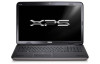
| 13 Disconnect the speaker cable from the connector on the I/O board. |
112 |
| 14 Turn the top-cover assembly over. |
112 |
| 15 Remove the three screws that secure the I/O board to the top cover. |
112 |
| 16 Carefully ease the connectors on the I/O board out of the slots in the top cover, and lift the I/O board off the top cover. |
112 |
| Replacing the I/O Board |
113 |
| 1 Follow the instructions in \ |
113 |
| 2 Align the connectors on the I/O board with the slots on the top cover and place the I/O board on the top cover. |
113 |
| 3 Press the I/O board down to connect it to the system-board connector. |
113 |
| 4 Replace the three screws that secure the I/O board to the top cover. |
113 |
| 5 Connect the speaker cable to the connector on the I/O board. |
113 |
| 6 Follow the instructions from step 11 to step 15 in \ |
113 |
| 7 Replace the bluetooth card (see \ |
113 |
| 8 Replace the Mini-Card(s) (see \ |
113 |
| 9 Replace the display assembly (see \ |
114 |
| 10 Replace the keyboard (see \ |
114 |
| 11 Replace the palm-rest assembly (see \ |
114 |
| 12 Replace the optical drive (see \ |
114 |
| 13 Follow the instructions in step 5 in \ |
114 |
| 14 Replace the memory module(s) (see \ |
114 |
| 15 Replace the module cover (see \ |
114 |
| 16 Replace the battery (see \ |
114 |
| 22 |
115 |
| TV Antenna Connector |
115 |
| Removing the TV Antenna Connector |
115 |
| 1 Follow the instructions in \ |
115 |
| 2 Remove the battery (see \ |
115 |
| 3 Remove the module cover (see \ |
115 |
| 4 Remove the memory module(s) (see \ |
115 |
| 5 Follow the instructions in step 5 in \ |
115 |
| 6 Remove the optical drive (see \ |
115 |
| 7 Remove the palm-rest assembly (see \ |
115 |
| 8 Remove the keyboard (see \ |
115 |
| 9 Remove the display assembly (see \ |
115 |
| 10 Remove the Mini-Card(s) (see \ |
115 |
| 11 Remove the bluetooth card (see \ |
116 |
| 12 Follow the instructions from step 13 to step 18 in \ |
116 |
| 13 Disconnect the speaker cable from the connector on the I/O board. |
116 |
| 14 Turn the top-cover assembly over. |
116 |
| 15 Remove the I/O board (see \ |
116 |
| 16 Make note of the TV antenna connector cable routing and remove the cable from the routing guides. |
116 |
| 17 Remove the two screws that secure the TV antenna connector to the top cover. |
116 |
| 18 Carefully ease the TV antenna connector off the slot in the top cover and lift it off the top cover. |
117 |
| Replacing the TV Antenna Connector |
117 |
| 1 Follow the instructions in \ |
117 |
| 2 Align the TV antenna connector with the slot on the top cover and place the TV antenna connector on the top cover. |
117 |
| 3 Replace the two screws that secure the TV antenna connector to the top cover. |
117 |
| 4 Route the TV antenna connector cable through the routing guides. |
117 |
| 5 Replace the I/O board (see \ |
117 |
| 6 Connect the speaker cable to the connector on the I/O board. |
117 |
| 7 Follow the instructions from step 11 to step 15 in \ |
118 |
| 8 Replace the bluetooth card (see \ |
118 |
| 9 Replace the Mini-Card(s) (see \ |
118 |
| 10 Replace the display assembly (see \ |
118 |
| 11 Replace the keyboard (see \ |
118 |
| 12 Replace the palm-rest assembly (see \ |
118 |
| 13 Replace the optical drive (see \ |
118 |
| 14 Follow the instructions in step 5 in \ |
118 |
| 15 Replace the memory module(s) (see \ |
118 |
| 16 Replace the module cover (see \ |
118 |
| 17 Replace the battery (see \ |
118 |
| 23 |
119 |
| USB Board |
119 |
| Removing the USB Board |
119 |
| 1 Follow the instructions in \ |
119 |
| 2 Remove the battery (see \ |
119 |
| 3 Remove the module cover (see \ |
119 |
| 4 Remove the memory module(s) (see \ |
119 |
| 5 Follow the instructions in step 5 in \ |
119 |
| 6 Remove the optical drive (see \ |
119 |
| 7 Remove the palm-rest assembly (see \ |
119 |
| 8 Remove the keyboard (see \ |
119 |
| 9 Remove the display assembly (see \ |
119 |
| 10 Remove the Mini-Card(s) (see \ |
119 |
| 11 Remove the bluetooth card (see \ |
120 |
| 12 Follow the instructions from step 13 to step 18 in \ |
120 |
| 13 Turn the top-cover assembly over. |
120 |
| 14 Lift the connector latch and disconnect the USB-board cable from the connector on the USB board. |
120 |
| 15 Remove the screw that secures the USB board to the top cover. |
120 |
| 16 Carefully ease the connectors on the USB board out of the slots in the top cover, and lift the USB board off the top cover. |
120 |
| Replacing the USB Board |
120 |
| 1 Follow the instructions in \ |
120 |
| 2 Align the connectors on the USB board with the slots on the top cover and place the USB board on the top cover. |
121 |
| 3 Replace the screw that secures the USB board to the top cover. |
121 |
| 4 Slide the USB-board cable into the connector on the USB board and press the connector latch down to secure the cable. |
121 |
| 5 Follow the instructions from step 11 to step 15 in \ |
121 |
| 6 Replace the bluetooth card (see \ |
121 |
| 7 Replace the Mini-Card(s) (see \ |
121 |
| 8 Replace the display assembly (see \ |
121 |
| 9 Replace the keyboard (see \ |
121 |
| 10 Replace the palm-rest assembly (see \ |
121 |
| 11 Replace the optical drive (see \ |
121 |
| 12 Follow the instructions in step 5 in \ |
121 |
| 13 Replace the memory module(s) (see \ |
121 |
| 14 Replace the module cover (see \ |
121 |
| 15 Replace the battery (see \ |
121 |
| 24 |
123 |
| System Board |
123 |
| Removing the System Board |
123 |
| 1 Follow the instructions in \ |
123 |
| 2 Remove any installed card or blank from the Media Card Reader. |
123 |
| 3 Remove the battery (see \ |
123 |
| 4 Remove the module cover (see \ |
123 |
| 5 Remove the memory module(s) (see \ |
123 |
| 6 Follow the instructions in step 5 in \ |
123 |
| 7 Remove the optical drive (see \ |
123 |
| 8 Remove the palm-rest assembly (see \ |
123 |
| 9 Remove the keyboard (see \ |
123 |
| 10 Remove the display assembly (see \ |
124 |
| 11 Remove the Mini-Card(s) (see \ |
124 |
| 12 Remove the bluetooth card (see \ |
124 |
| 13 Remove the coin-cell battery (see \ |
124 |
| 14 Lift the connector latch and pull the pull-tab to disconnect the USB-board cable from the system-board connector. |
124 |
| 15 Follow the instructions from step 13 to step 18 in \ |
124 |
| 16 Remove the heat sink (see \ |
124 |
| 17 Remove the processor module (see \ |
124 |
| 18 Remove the I/O board (see \ |
125 |
| 19 Disconnect the fan cable and AC-adapter connector cable from their connectors on the system board. |
125 |
| 20 Remove the screw that secures the system board to the top cover. |
125 |
| 21 Lift the system board off the top cover. |
125 |
| Replacing the System Board |
125 |
| 1 Follow the instructions in \ |
125 |
| 2 Align the screw hole on the system board with the screw hole on the top cover. |
125 |
| 3 Replace the screw that secures the system board to the top cover. |
125 |
| 4 Connect the fan cable and AC-adapter connector cable to their connectors on the system board. |
126 |
| 5 Replace the I/O board (see \ |
126 |
| 6 Replace the processor module (see \ |
126 |
| 7 Replace the heat sink (see \ |
126 |
| 8 Follow the instructions from step 11 to step 15 in \ |
126 |
| 9 Slide the USB-board cable into the system-board connector and press down on the connector latch to secure the cable. |
126 |
| 10 Replace the coin-cell battery (see \ |
126 |
| 11 Replace the bluetooth card (see \ |
126 |
| 12 Replace the Mini-Card(s) (see \ |
126 |
| 13 Replace the display assembly (see \ |
126 |
| 14 Replace the keyboard (see \ |
126 |
| 15 Replace the palm-rest assembly (see \ |
126 |
| 16 Replace the optical drive (see \ |
126 |
| 17 Follow the instructions in step 5 in \ |
126 |
| 18 Replace the memory module(s) (see \ |
126 |
| 19 Replace the module cover (see \ |
126 |
| 20 Replace the battery (see \ |
126 |
| 21 Replace any blank or card you removed from the Media Card Reader. |
126 |
| 22 Turn on the computer. |
126 |
| 23 Enter the service tag (see \ |
127 |
| Entering the Service Tag in the BIOS |
127 |
| 1 Ensure that the AC adapter is plugged in and that the main battery is installed properly. |
127 |
| 2 Turn on the computer. |
127 |
| 3 Press <F2> during POST to enter the system setup program. |
127 |
| 4 Navigate to the security tab and enter the service tag in the Set Service Tag field. |
127 |
| 25 |
129 |
| Speakers |
129 |
| Removing the Speakers |
129 |
| 1 Follow the instructions in \ |
129 |
| 2 Remove the battery (see \ |
129 |
| 3 Disconnect the speaker cable from the I/O board connector. |
129 |
| 4 Remove the system board (see \ |
130 |
| 5 Make note of the speakers cable routing and remove the cable from the routing guides. |
130 |
| 6 Remove the four screws (two on each speaker) that secure the speakers to the top cover. |
130 |
| 7 Lift the speakers along with the cable off the top cover. |
130 |
| Replacing the Speaker |
131 |
| 1 Follow the instructions in \ |
131 |
| 2 Route the speakers cable through the routing guides |
131 |
| 3 Align the screw holes on the speakers with the screw holes on the top cover. |
131 |
| 4 Replace the four screws (two on each speaker) that secure the speakers to the base cover. |
131 |
| 5 Replace the system board (see \ |
131 |
| 6 Connect the speaker cable to the system-board connector. |
131 |
| 7 Replace the battery (see \ |
132 |
| 26 |
133 |
| Flashing the BIOS |
133 |
| 1 Turn on the computer. |
133 |
| 2 Go to support.dell.com/support/downloads. |
133 |
| 3 Locate the BIOS update file for your computer: |
133 |
| a Click Enter a Tag. |
133 |
| b Enter your computer’s Service Tag in the Enter a service tag: field, click Go, and proceed to step 4. |
133 |
| a Click Select Model. |
133 |
| b Select the type of product in the Select Your Product Family list. |
133 |
| c Select the product brand in the Select Your Product Line list. |
133 |
| d Select the product model number in the Select Your Product Model list. |
133 |
| e Click Confirm. |
133 |
| 4 A list of results appear on the screen. Click BIOS. |
133 |
| 5 Click Download Now to download the latest BIOS file. The File Download window appears. |
133 |
| 6 Click Save to save the file on your desktop. The file downloads to your desktop. |
133 |
| 7 Click Close if the Download Complete window appears. The file icon appears on your desktop and is titled the same as the downloaded BIOS update file. |
133 |
 1
1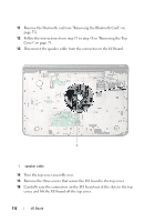 112
112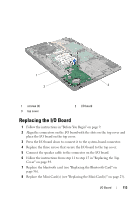 113
113 114
114 115
115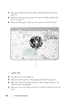 116
116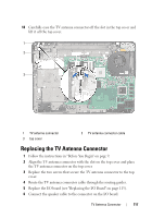 117
117 118
118 119
119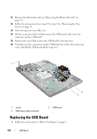 120
120 121
121 122
122

