Dell XPS M170 MXG051 XPS/Inspiron M170 Service Manual
Dell XPS M170 MXG051 Manual
 |
View all Dell XPS M170 MXG051 manuals
Add to My Manuals
Save this manual to your list of manuals |
Dell XPS M170 MXG051 manual content summary:
- Dell XPS M170 MXG051 | XPS/Inspiron M170 Service Manual - Page 1
Dell™ XPS M170 Service Manual Before You Begin System Components Optical Drive Hard Drive Memory Help file. To access the help file, click the Start button, click Help and Support, click User and system guides, click User's guides, and click Dell Help. If you purchased a Dell™ n Series computer, any - Dell XPS M170 MXG051 | XPS/Inspiron M170 Service Manual - Page 2
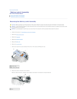
Dell™ XPS M170 Service Manual Removing the Battery Latch Assembly Replacing the Battery Latch Assembly Removing the Battery Latch Assembly CAUTION: Before you begin any of the procedures in this section, follow the safety instructions located in the Product Information Guide. NOTICE: To avoid - Dell XPS M170 MXG051 | XPS/Inspiron M170 Service Manual - Page 3
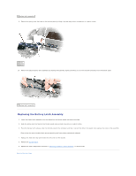
2 battery latch assembly 9. Remove the spring from the hook on the bottom panel by lifting it up and away with a screwdriver or a plastic scribe. 1 hook 2 spring 10. Remove the plastic battery latch assembly by twisting the assembly slightly and lifting it out of the channel and away from the bottom - Dell XPS M170 MXG051 | XPS/Inspiron M170 Service Manual - Page 4
Before You Begin Dell™ Inspiron™ XPS Service Manual Recommended Tools Turning Off Your Computer Before Before you begin any of the procedures in this section, follow the safety instructions in the Product Information Guide. NOTICE: Handle components and cards with care. Do not touch the components - Dell XPS M170 MXG051 | XPS/Inspiron M170 Service Manual - Page 5
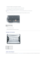
and turn the computer upside down on a flat work surface. NOTICE: To avoid damaging the system board, you must remove the main battery before you service the computer. 6. Slide the battery-bay latch release on the bottom of the computer and remove the battery from the bay. 1 battery-bay latch - Dell XPS M170 MXG051 | XPS/Inspiron M170 Service Manual - Page 6
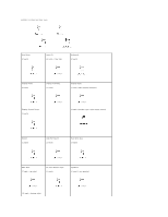
number of screws and their sizes. Hard Drive: (2 each) Fans (2): (4 total - 2 per fan) Keyboard: (2 each) Display Panel: (8 each) Display Assembly: (4 each) Display Bezel: (4 each, under display bumpers) Display Ground Screw: (1 each) (4 each, shoulder type, under screw covers) Modem: (1 - Dell XPS M170 MXG051 | XPS/Inspiron M170 Service Manual - Page 7
Optical Drive: (1 each) System Board: (4 each) Door to Card with Bluetooth® Wireless Technology (1 each) Back to Contents Page - Dell XPS M170 MXG051 | XPS/Inspiron M170 Service Manual - Page 8
to Contents Page Flashing the BIOS Dell™ XPS M170 Service Manual NOTICE: Plug the AC adapter into a known good not interrupt this process once it begins. Doing so may cause system damage. Follow the instructions that appear on the screen. The computer continues to boot and updates the new BIOS. - Dell XPS M170 MXG051 | XPS/Inspiron M170 Service Manual - Page 9
Card With Bluetooth® Wireless Technology Dell™ XPS M170 Service Manual Removing the Card Replacing the Card Removing the Card CAUTION: Before you begin the following procedure, see the safety instructions in the Product Information Guide. NOTICE: To avoid electrostatic discharge, ground yourself by - Dell XPS M170 MXG051 | XPS/Inspiron M170 Service Manual - Page 10
Coin-Cell Battery Dell™ Inspiron™ XPS Service Manual Removing the Coin-Cell Battery Replacing the Coin-Cell battery Removing the Coin-Cell Battery CAUTION: Before you begin the following procedure, see the safety instructions in the Product Information Guide. NOTICE: To avoid electrostatic discharge - Dell XPS M170 MXG051 | XPS/Inspiron M170 Service Manual - Page 11
Back to Contents Page - Dell XPS M170 MXG051 | XPS/Inspiron M170 Service Manual - Page 12
Service Manual Removing the Microprocessor Module Replacing the Microprocessor Module Removing the Microprocessor Module CAUTION: Before you begin the following procedure, see the safety instructions in the Product Information Guide the computer. 1. Follow the instructions in "Before Working Inside - Dell XPS M170 MXG051 | XPS/Inspiron M170 Service Manual - Page 13
NOTE: The ZIF-socket cam screw secures the microprocessor to the system board. Take note of the arrow on the ZIF-socket cam screw, which indicates the direction to turn the cam screw. 8. Lift the microprocessor module from the ZIF socket. Replacing the Microprocessor Module NOTICE: Ensure that the - Dell XPS M170 MXG051 | XPS/Inspiron M170 Service Manual - Page 14
Page Display Dell™ XPS M170 Service Manual Display Assembly Display Bezel Display Panel Display Latch Display Assembly Removing the Display Assembly CAUTION: Before you begin the following procedure, see the safety instructions in the Product Information Guide. NOTICE: To avoid electrostatic - Dell XPS M170 MXG051 | XPS/Inspiron M170 Service Manual - Page 15
1 antenna cables 4. Turn the computer top-side up. 5. Remove the center control cover. 6. Open the display all the way (180 degrees) so that it lies flat against the work surface. 7. Use the pull-tab to disconnect the display cable, and then disengage the display cable from the cable channel. 8. Use - Dell XPS M170 MXG051 | XPS/Inspiron M170 Service Manual - Page 16
10. Lift the display assembly away from the computer. Replacing the Display Assembly 1. Align the display assembly over the screw holes in the base of the computer. 2. Thread the Mini PCI antenna cables back through the hole in the base of the computer. 3. Replace the four M2.5 x 5-mm screws. 4. - Dell XPS M170 MXG051 | XPS/Inspiron M170 Service Manual - Page 17
bumpers (6) 4 shoulder screws (2) Removing the Display Bezel CAUTION: Before you begin the following procedure, see the safety instructions in the Product Information Guide. NOTICE: To avoid electrostatic discharge, ground yourself by using a wrist grounding strap or by periodically touching an - Dell XPS M170 MXG051 | XPS/Inspiron M170 Service Manual - Page 18
1 tabs 7. Repeat step 6 for the lower-left corner of the bezel. Then use your fingers to release the snaps around the rest of the bezel and lift it away from the cover. 1 display bezel 2 display panel Replacing the Display Bezel 1. Starting at any corner, use your fingers to gently snap the bezel - Dell XPS M170 MXG051 | XPS/Inspiron M170 Service Manual - Page 19
mm screws (8) 4 display back cover Removing the Display Panel CAUTION: Before you begin the following procedure, see the safety instructions in the Product Information Guide. NOTICE: To avoid electrostatic discharge, ground yourself by using a wrist grounding strap or by touching an unpainted metal - Dell XPS M170 MXG051 | XPS/Inspiron M170 Service Manual - Page 20
the display bezel. Display Latch Removing the Display Latch CAUTION: Before you begin the following procedure, see the safety instructions in the Product Information Guide. NOTICE: To avoid electrostatic discharge, ground yourself by using a wrist grounding strap or by touching an unpainted metal - Dell XPS M170 MXG051 | XPS/Inspiron M170 Service Manual - Page 21
to Contents Page System Fans Dell™ XPS M170 Service Manual Removing the System Fans Replacing the System Fans Removing the System Fans CAUTION: Before you begin the following procedure, see the safety instructions in the Product Information Guide. NOTICE: To avoid electrostatic discharge, ground - Dell XPS M170 MXG051 | XPS/Inspiron M170 Service Manual - Page 22
1 fan 2 M2.5 x 5-mm screws (2) 3 LED system board connector 4 fan system board connector Replacing the System Fans 1. Align and place each fan over its respective screw holes on the system board. 2. Replace the four M2.5 x 5-mm screws (two on each fan). 3. Connect the cables for each fan to the - Dell XPS M170 MXG051 | XPS/Inspiron M170 Service Manual - Page 23
XPS M170 Service Manual Removing the begin the following procedure, see the safety instructions in the Product Information Guide. NOTICE: To avoid damaging the system board or provide support for hard drives from sources other than Dell. Removing the Hard Drive 1. Follow the instructions in "Before - Dell XPS M170 MXG051 | XPS/Inspiron M170 Service Manual - Page 24
Returning a Hard Drive to Dell Return your old hard drive to Dell in its original or comparable foam packaging. Otherwise, the hard drive may be damaged in transit. 1 hard drive 2 foam packaging Back to Contents Page - Dell XPS M170 MXG051 | XPS/Inspiron M170 Service Manual - Page 25
Cover Dell™ XPS M170 Service Manual Removing the Center Control Cover Replacing the Center Control Cover Removing the Center Control Cover CAUTION: Before you begin any of the procedures in this section, follow the safety instructions located in the Product Information Guide. NOTICE: To avoid - Dell XPS M170 MXG051 | XPS/Inspiron M170 Service Manual - Page 26
Back to Contents Page Keyboard Dell™ XPS M170 Service Manual Removing the Keyboard Replacing the Keyboard Removing the Keyboard CAUTION: Before you begin the following procedure, see the safety instructions in the Product Information Guide. NOTICE: To avoid electrostatic discharge, ground yourself - Dell XPS M170 MXG051 | XPS/Inspiron M170 Service Manual - Page 27
display panel. 1. Reconnect the keyboard to the system board connector. 2. Slide the bottom of the keyboard into the computer base. NOTE: You may need to push the bottom of the keyboard down slightly to seat the keyboard into the computer base. 3. Replace the two M2.5 x 5-mm screws across the top of - Dell XPS M170 MXG051 | XPS/Inspiron M170 Service Manual - Page 28
Back to Contents Page Customizable LEDs Dell™ XPS M170 Service Manual Replacing the Customizable LEDs The system has 3 pairs (total of 6) of Light Emitting Diode sets (LEDs) that can be customized to display a chosen color. These - Dell XPS M170 MXG051 | XPS/Inspiron M170 Service Manual - Page 29
Page MCH Heat Sink Dell™ XPS M170 Service Manual Removing the MCH Heat Sink Replacing the MCH Heat Sink Removing the MCH Heat Sink CAUTION: Before you perform the following procedures, see the safety instructions in the Product Information Guide. NOTICE: To avoid electrostatic discharge, ground - Dell XPS M170 MXG051 | XPS/Inspiron M170 Service Manual - Page 30
- Dell XPS M170 MXG051 | XPS/Inspiron M170 Service Manual - Page 31
Contents Page Memory Module Dell™ XPS M170 Service Manual Removing the Memory Module Replacing the Memory Module Removing the Memory Module CAUTION: Before you begin the following procedure, see the safety instructions in the Product Information Guide. NOTICE: To prevent static damage to components - Dell XPS M170 MXG051 | XPS/Inspiron M170 Service Manual - Page 32
Replacing the Memory Module NOTE: To get maximum performance/dual-channel memory bandwidth capability, both memory module connectors must contain memory modules and the modules must be of the same size and configuration. NOTE: If a memory module is not installed properly, the computer will not boot. - Dell XPS M170 MXG051 | XPS/Inspiron M170 Service Manual - Page 33
Service Manual Removing the Mini PCI Card Replacing the Mini PCI Card Removing the Mini PCI Card CAUTION: If you are removing and/or installing a 2.4-GHz (802.11b, 802.11b/g) Mini PCI card, follow the instructions follow the safety instructions located in the Product Information Guide. NOTICE: To - Dell XPS M170 MXG051 | XPS/Inspiron M170 Service Manual - Page 34
NOTICE: To prevent damage to the Mini PCI card connector, do not use tools to spread the securing clips that secure the card. 5. Release the Mini PCI card by spreading the metal securing tabs until the card pops up slightly. 6. Remove the Mini PCI card from the connector at a 45-degree angle. 1 Mini - Dell XPS M170 MXG051 | XPS/Inspiron M170 Service Manual - Page 35
1 antenna cables (2) 3. Replace the cover. Back to Contents Page - Dell XPS M170 MXG051 | XPS/Inspiron M170 Service Manual - Page 36
to Contents Page Modem Dell™ XPS M170 Service Manual Removing the Modem Replacing the Modem Removing the Modem CAUTION: Before you begin any of the procedures in this section, follow the safety instructions located in the Product Information Guide. NOTICE: To avoid electrostatic discharge, ground - Dell XPS M170 MXG051 | XPS/Inspiron M170 Service Manual - Page 37
NOTICE: Do not disconnect the modem cable from the system board. 5. Disconnect the modem cable from the modem. Replacing the Modem 1. Connect the modem cable to the modem. NOTICE: Ensure that the modem cable is routed correctly when you replace the modem. 2. Connect the modem to the system board. - Dell XPS M170 MXG051 | XPS/Inspiron M170 Service Manual - Page 38
Contents Page Optical Drive Dell™ XPS M170 Service Manual Removing the Optical Drive Replacing the Optical Drive . Avoid pressing down on them or placing heavy objects on top of them. 1. Follow the instructions in "Before Working Inside Your Computer." 2. Turn over the computer and remove the M2.5 x - Dell XPS M170 MXG051 | XPS/Inspiron M170 Service Manual - Page 39
to Contents Page Palm Rest Dell™ XPS M170 Service Manual Removing the Palm Rest Replacing the Palm Rest Removing the Palm Rest CAUTION: Before you begin the following procedure, see the safety instructions in the Product Information Guide. NOTICE: To avoid electrostatic discharge, ground yourself by - Dell XPS M170 MXG051 | XPS/Inspiron M170 Service Manual - Page 40
1 M2.5 x 8-mm screws (11) 9. Remove the Internal Card With Bluetooth® Wireless Technology. 10. Turn the computer top-side up and disconnect the touch-pad connector from the system board. 11. Remove the LED board connector. 12. Lift the palm rest and remove it from the computer. 1 touch-pad connector - Dell XPS M170 MXG051 | XPS/Inspiron M170 Service Manual - Page 41
8. Replace the display assembly. 9. Replace the keyboard. 10. Replace the center control cover. Back to Contents Page - Dell XPS M170 MXG051 | XPS/Inspiron M170 Service Manual - Page 42
Page PC Card Reader Cage Dell™ XPS M170 Service Manual Removing the PC Card Reader cage Removing the PC Card Reader cage CAUTION: Before you begin the following procedure, see the safety instructions in the Product Information Guide. NOTICE: To avoid electrostatic discharge, ground yourself by - Dell XPS M170 MXG051 | XPS/Inspiron M170 Service Manual - Page 43
Back to Contents Page Pin Assignments for I/O Connectors Dell™ XPS M170 Service Manual USB Connector Video Connector S-Video TV-Out Connector IEEE 1394 Connector USB Connector Pin Signal 1 USB5V+ 2 USBP- 3 USBP+ 4 GND Video Connector Pin Signal Pin Signal 1 - Dell XPS M170 MXG051 | XPS/Inspiron M170 Service Manual - Page 44
2 GND 3 DLUMA-L 4 DCRMA-L Composite Video Pin Signal 5 NC 6 DCMPS-L 7 GND IEEE 1394 Connector Pin Signal 1 TPB- 2 TPB+ 3 TPA- 4 TPA+ Back to Contents Page - Dell XPS M170 MXG051 | XPS/Inspiron M170 Service Manual - Page 45
Contents Page Speakers Dell™ XPS M170 Service Manual Removing the Speakers Replacing the Speakers Removing the Speakers CAUTION: Before you begin any of the procedures in this section, follow the safety instructions located in the Product Information Guide. NOTICE: To avoid electrostatic discharge - Dell XPS M170 MXG051 | XPS/Inspiron M170 Service Manual - Page 46
4. Re-route the speaker cables into the cable guides and re-adhere the tape to secure the speaker cables in place on the computer base. Back to Contents Page - Dell XPS M170 MXG051 | XPS/Inspiron M170 Service Manual - Page 47
to Contents Page System Board Dell™ XPS M170 Service Manual Removing the System Board Replacing the System Board Removing the System Board CAUTION: Before you begin the following procedure, see the safety instructions in the Product Information Guide. NOTICE: To avoid electrostatic discharge, ground - Dell XPS M170 MXG051 | XPS/Inspiron M170 Service Manual - Page 48
1 PC Card connector 2 stiffener bracket screw 3 stiffener bracket 4 PC Card connector on system board 14. If applicable, remove the video card/thermal cooling assembly. NOTE: Remove the video card/thermal cooling assembly as a single unit. Do not separate the heat sink from the video card. 15. - Dell XPS M170 MXG051 | XPS/Inspiron M170 Service Manual - Page 49
the computer. 2. Turn on the computer. 3. Insert the flash BIOS update program CD that accompanied the replacement system board into the optical drive. Follow the instructions that appear on the screen. 4. Enter the system setup program to update the BIOS on the new system board with the computer - Dell XPS M170 MXG051 | XPS/Inspiron M170 Service Manual - Page 50
Back to Contents Page - Dell XPS M170 MXG051 | XPS/Inspiron M170 Service Manual - Page 51
Back to Contents Page System Components Dell™ XPS M170 Service Manual NOTICE: Only a certified service technician should perform repairs on your computer. Damage due to servicing that is not authorized by Dell is not covered by your warranty. NOTICE: Unless otherwise noted, each procedure in this - Dell XPS M170 MXG051 | XPS/Inspiron M170 Service Manual - Page 52
M170 Service Manual Removing the Microprocessor Thermal-Cooling Assembly Replacing the Microprocessor Thermal-Cooling Assembly Removing the Microprocessor Thermal-Cooling Assembly CAUTION: Before you begin the following procedure, see the safety instructions in the Product Information Guide. NOTICE - Dell XPS M170 MXG051 | XPS/Inspiron M170 Service Manual - Page 53
Back to Contents Page - Dell XPS M170 MXG051 | XPS/Inspiron M170 Service Manual - Page 54
Service Manual NOTE: A NOTE indicates important information that helps you make better use of your computer. NOTICE: A NOTICE indicates either potential damage to hardware or loss of data and tells you how to avoid the problem Help and Support, click User and system guides, click User's guides, and - Dell XPS M170 MXG051 | XPS/Inspiron M170 Service Manual - Page 55
USB Port Board Dell™ XPS M170 Service Manual Removing the USB Port Board Replacing the USB Port Board Removing the USB Port Board CAUTION: Before you begin any of the procedures in this section, follow the safety instructions located in the Product Information Guide. NOTICE: To avoid electrostatic - Dell XPS M170 MXG051 | XPS/Inspiron M170 Service Manual - Page 56
5. Replace the palm rest. 6. Replace the display assembly. 7. Replace the keyboard. 8. Replace the center control cover. 9. Replace the battery and other items removed in "Before Working Inside Your Computer." Back to Contents Page - Dell XPS M170 MXG051 | XPS/Inspiron M170 Service Manual - Page 57
XPS M170 Service Manual Removing the Video Card/Thermal Cooling Assembly Replacing the Video Card/Thermal Cooling Assembly Removing the Video Card/Thermal Cooling Assembly CAUTION: Before performing the following procedures, read the safety instructions in your Product Information Guide. NOTICE: To - Dell XPS M170 MXG051 | XPS/Inspiron M170 Service Manual - Page 58
2. Tighten the four captive screws on the video card/thermal cooling assembly. Back to Contents Page - Dell XPS M170 MXG051 | XPS/Inspiron M170 Service Manual - Page 59
Back to Contents Page Subwoofer Dell™ XPS M170 Service Manual Removing the Subwoofer Replacing the Subwoofer Removing the Subwoofer CAUTION: Before performing the following procedures, read the safety instructions in your Product Information Guide. NOTICE: To avoid electrostatic discharge, ground - Dell XPS M170 MXG051 | XPS/Inspiron M170 Service Manual - Page 60
Back to Contents Page
-
 1
1 -
 2
2 -
 3
3 -
 4
4 -
 5
5 -
 6
6 -
 7
7 -
8
-
9
-
10
-
11
-
12
-
13
-
14
-
15
-
16
-
17
-
18
-
19
-
20
-
21
-
22
-
23
-
24
-
25
-
26
-
27
-
28
-
29
-
30
-
31
-
32
-
33
-
34
-
35
-
36
-
37
-
38
-
39
-
40
-
41
-
42
-
43
-
44
-
45
-
46
-
47
-
48
-
49
-
50
-
51
-
52
-
53
-
54
-
55
-
56
-
57
-
58
-
59
-
60
 |
 |
Dell™ XPS M170 Service Manual
Before You Begin
System Components
Optical Drive
Hard Drive
Memory Module
Modem
Mini PCI Card
Internal Card With Bluetooth
®
Wireless Technology
Center Control Cover
Keyboard
Display
Palm Rest
Speakers
Subwoofer
USB Port Board
System Fans
Microprocessor Thermal
-
Cooling Assembly
Microprocessor Module
Video Card/Thermal Cooling Assembly
MCH Heat Sink
PC Card Reader Cage
System Board
Battery Latch Assembly
Customizable LEDs
Flashing the BIOS
Pin Assignments for I/O Connectors
Notes, Notices, and Cautions
Abbreviations and Acronyms
For a complete list of abbreviations and acronyms, see the
Dell Help
file. To access the help file, click the
Start
button, click
Help and Support
, click
User and
system guides
, click
User's guides
, and click
Dell Help
.
If you purchased a Dell™ n Series computer, any references in this document to Microsoft®
Windows
®
operating systems are not applicable.
Information in this document is subject to change without notice.
© 2005 Dell Inc. All rights reserved.
Reproduction in any manner whatsoever without the written permission of Dell Inc.
is strictly forbidden.
Trademarks used in this text:
Dell
and the
DELL
logo are trademarks of Dell Inc.;
Microsoft
and
Windows
are registered trademarks of Microsoft Corporation;
Bluetooth
is a
trademark owned by Bluetooth SIG, Inc. and is used by Dell Inc. under license.
Other trademarks and trade names may be used in this document to refer to either the entities claiming the marks and names or their products. Dell Inc. disclaims any
proprietary interest in trademarks and trade names other than its own.
Model PP14L
September 2005 Rev. A00
NOTE:
A NOTE indicates important information that helps you make better use of your computer.
CAUTION:
A CAUTION indicates a potential for property damage, personal injury, or death.