Denon AVR-3805 Owners Manual - Page 8
Connecting the video components - digital output
 |
UPC - 081757505987
View all Denon AVR-3805 manuals
Add to My Manuals
Save this manual to your list of manuals |
Page 8 highlights
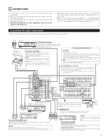
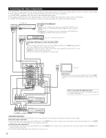
Connecting the video components • To connect the video signal, connect using a 75 Ω/ohms video signal cable cord. Using an improper cable can result in a drop in video quality. • When making connections, also refer to the operating instructions of the other components. • The AVR-3805 is equipped with a function for up-converting video signals. • The signal connected to the video signal terminal is output to the S-Video and component video monitor out terminals. • The REC OUT terminals have no conversion function, so when recording only connect the video terminals. AUDIO VIDEO OUT R L OUT TV or DBS tuner B RL Connecting a TV or DBS tuner TV or DBS • Connect the TV's or DBS tuner's video output jack (VIDEO OUTPUT) to the VIDEO (yellow) TV or DBS IN jack using a 75 Ω/ohms video coaxial pin plug cord. • Connect the TV's or DBS tuner's audio output jacks (AUDIO OUTPUT) to the AUDIO TV or DBS IN jacks using pin plug cords. AUDIO VIDEO B OUT R L OUT DVD player or video disc player (VDP), etc. RL Connecting a DVD player or a video disc player (VDP) DVD • Connect the video disc player's video output jack (VIDEO OUTPUT) to the VIDEO (yellow) DVD IN jack using a 75 Ω/ohms video coaxial pin plug cord. • Connect the video disc player's analog audio output jacks (ANALOG AUDIO OUTPUT) to the AUDIO DVD IN jacks using pin plug cords. • VDP can be connected to the VDP jacks in the same way. R L R L L R R L RL RL R LRL Video deck 2 R L R L OUT IN OUT IN AUDIO VIDEO VIDEO IN Monitor TV MONITOR OUT • Connect the TV's video input jack (VIDEO INPUT) to the VIDEO MONITOR OUT jack using a 75 Ω/ohms video coaxial pin plug cord. Note on connecting the digital input jacks • Only audio signals are inputs to the digital input jacks. For details. (See page 7) R LR L Video deck 1 R L R L OUT IN OUT IN AUDIO VIDEO Connecting a video decks • There are two sets of video deck (VCR) jacks, so two video decks can be connected for simultaneous recording or video copying. Video input/output connections: • Connect the video deck's video output jack (VIDEO OUT) to the VIDEO (yellow) VCR-1 IN jack, and the video deck's video input jack (VIDEO IN) to the VIDEO (yellow) VCR-1 OUT jack using 75 Ω/ohms video coaxial pin plug cords. Connecting the audio output jacks • Connect the video deck's audio output jacks (AUDIO OUT) to the AUDIO VCR-1 IN jacks, and the video deck's audio input jacks (AUDIO IN) to the AUDIO VCR-1 OUT jacks using pin plug cords. Connect the second video deck to the VCR-2 jacks in the same way. 8
-
 1
1 -
2
-
 3
3 -
 4
4 -
 5
5 -
 6
6 -
 7
7 -
 8
8 -
 9
9 -
 10
10 -
 11
11 -
 12
12 -
 13
13 -
14
-
15
-
16
-
17
-
18
-
19
-
20
-
21
-
22
-
23
-
24
-
25
-
26
-
27
-
28
-
29
-
30
-
31
-
32
-
33
-
34
-
35
-
36
-
37
-
38
-
39
-
40
-
41
-
42
-
43
-
44
-
45
-
46
-
47
-
48
-
49
-
50
-
51
-
52
-
53
-
54
-
55
-
56
-
57
-
58
-
59
-
60
-
61
-
62
-
63
-
64
-
65
-
66
-
67
-
68
-
69
-
70
-
71
-
72
-
73
-
74
-
75
-
76
-
77
-
78
-
79
-
80
-
81
-
82
-
83
-
84
-
85
-
86
-
87
-
88
-
89
-
90
-
91
-
92
-
93
-
94
-
95
-
96
-
97
-
98
-
99
-
100
-
101
-
102
-
103
-
104
 |
 |
