Dewalt D25133K Instruction Manual - Page 2
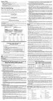
Forward/Reverse Lever Fig. 1 - hammer drill
 |
View all Dewalt D25133K manuals
Add to My Manuals
Save this manual to your list of manuals |
Page 2 highlights
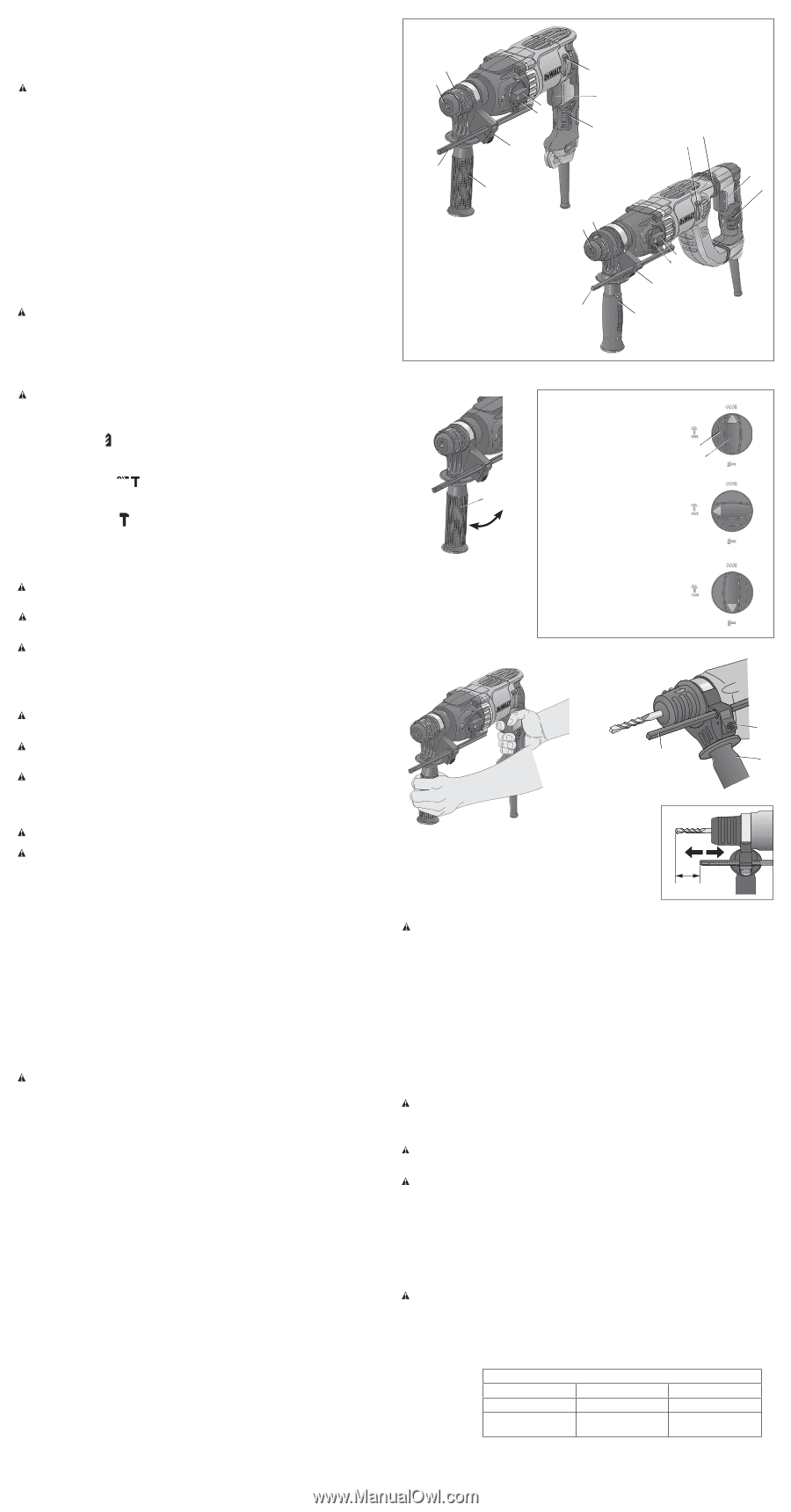
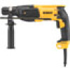
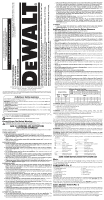
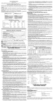
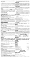
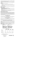
Mechanical Clutch All rotary hammer drills are equipped with a torque limiting clutch that reduces the maximum torque reaction transmitted to the operator in case of jamming of a drill bit. This feature also prevents the gearing and electric motor from stalling. The torque limiting clutch has been factory-set and cannot be adjusted. Side Handle (Fig. 2) WARNING: To reduce the risk of personal injury, ALWAYS operate the tool with the side handle properly installed and securely tightened. Failure to do so may result in the side handle slipping during tool operation and subsequent loss of control. Hold tool with both hands to maximize control. A side handle comes assembled with this rotary hammer. The side handle (H) can be fitted to suit both right-hand and left-hand users. TO ADJUST THE SIDE HANDLE 1. Loosen the side handle (H) by turning it counterclockwise. 2. Rotate the side handle to the desired position. 3. Tighten the side handle by turning it clockwise. Trigger Switch (Fig. 1) To start the rotary hammer, depress the variable speed trigger switch (A). To stop rotary hammer, release the switch. NOTE: Use lower speeds for starting holes without a centerpunch, drilling in metal, plastics or ceramics, or driving screws. Higher speeds are better for drilling in masonry for maximum efficiency. VARIABLE SPEED The variable speed trigger switch (A) permits speed control. The farther the trigger switch is depressed, the higher the speed of the drill. Forward/Reverse Lever (Fig. 1) The forward/reverse lever (C) is used to reverse the rotary hammer for backing out fasteners or jammed bits in drill-only mode. CAUTION: When reversing to clear jammed bits, be ready for strong reactive torque. To reverse the rotary hammer, turn it off and align the forward/reverse lever (C) with the yellow arrow pointing backward (viewed when holding drill in operating position). To position the lever for forward operation, turn the rotary hammer off and align the forward/reverse lever (C) with the yellow arrow pointing forward (viewed when holding drill in operating position). Mode Selector (Fig. 3) D25133, D25260, D25262, D25263 WARNING: Do not operate in drill or hammerdrill mode with a chisel bit in the chuck. Personal injury and damage to tool may result. NOTICE: Tool must come to a complete stop before activating the mode selector button or damage to the tool may result. DRILL-ONLY MODE To use drill-only mode, press mode selector button (E) and turn the mode selector (D) so the yellow arrow points to the corresponding symbol as shown. Use drill-only mode for wood, metal, and plastics. HAMMERDRILL MODE To use hammerdrill mode, press the mode selector button (E) and turn the mode selector (D) so the yellow arrow points to the corresponding symbol as shown. Use this mode for masonry drilling. HAMMER-ONLY MODE For light chiseling, press the mode selector button (E) and turn the mode selector (D) so the yellow arrow points to the corresponding symbol as shown. NOTE: The yellow arrow on the mode selector MUST be aligned with the one of the symbols at all times. There are no operable positions between the positions. SDS Plus Chuck (Fig. 1) WARNING: To reduce the risk of serious personal injury, turn tool off and disconnect tool from power source before making any adjustments or removing/installing attachments or accessories. WARNING: Burn Hazard. ALWAYS wear gloves when changing bits. Accessible metal parts on the tool and bits may get extremely hot during operation. Small bits of broken material may damage bare hands. WARNING: Do not attempt to tighten or loosen drill bits (or any other accessory) by gripping the front part of the chuck and turning the tool on. Damage to the chuck and personal injury may occur. To insert bit, insert shank of bit about 3/4" (19 mm), no further than 7/8" (24 mm) into chuck (F). Push and rotate bit until it locks in place. The bit will be securely held. To release bit, pull the chuck sleeve (F) back and remove the bit. OPERATION WARNING: To reduce the risk of injury, turn unit off and disconnect it from power source before installing and removing accessories, before adjusting or when making repairs. An accidental start-up can cause injury. WARNING: To reduce the risk of personal injury, ALWAYS ensure workpiece is anchored or clamped firmly. If drilling thin material, use a wood "back-up" block to prevent damage to the material. WARNING: To reduce the risk of personal injury, ALWAYS operate the tool with the side handle properly installed and securely tightened. Failure to do so may result in the side handle slipping during tool operation and subsequent loss of control. Hold tool with both hands to maximize control. Proper Hand Position (Fig. 1, 4) WARNING: To reduce the risk of serious personal injury, ALWAYS use proper hand position as shown. WARNING: To reduce the risk of serious personal injury, ALWAYS hold securely in anticipation of a sudden reaction. Proper hand position requires one hand on the side handle (H), with the other hand on the main handle (B). Drilling Tools The machine is intended for hammerdrilling in concrete, brick and stone. It is also suitable for drilling without impact in wood, metal, ceramic and plastic. Chipping Tools The machine is intended for chipping in concrete, brick and stone. Drilling Press mode selector button (E) and turn the mode selector (D) to the drill bit symbol for drilling, to the hammer symbol for hammering or to the hammerdrill symbol for hammerdrilling. DRILLING OPERATION 1. For WOOD, use twist bits, spade bits, power auger bits or hole saws. For METAL, use high-speed steel twist drill bits or hole saws. Use a cutting lubricant when drilling metals. The exceptions are cast iron and brass which should be drilled dry. For MASONRY, use carbide-tipped bits or masonry bits. A smooth, even flow of dust indicates the proper drilling rate. 2. Always apply pressure in a straight line with the bit. Use enough pressure to keep the drill bit biting, but do not push hard enough to stall the motor or deflect the bit. 3. Hold tool firmly with both hands to control the twisting action of the drill. WARNING: Drill may stall if overloaded causing a sudden twist. Always expect the stall. Grip the drill firmly with both hands to control the twisting action and avoid injury. 4. IF DRILL STALLS, it is usually because it is being overloaded. RELEASE TRIGGER IMMEDIATELY, remove drill bit from work, and determine cause of stalling. DO NOT CLICK TRIGGER OFF AND ON IN AN ATTEMPT TO START A STALLED DRILL - THIS CAN DAMAGE THE DRILL. 5. To minimize stalling or breaking through the material, reduce pressure on drill and ease the bit through the last fractional part of the hole. 6. Keep the motor running when pulling the bit back out of a drilled hole. This will help prevent jamming. 7. With variable speed drills there is no need to center punch the point to be drilled. Use a slow speed to start the hole and accelerate by squeezing the trigger harder when the hole is deep enough to drill without the bit skipping out. DRILLING IN METAL An SDS Plus round shank adaptor chuck is required for metal drilling. Ensure that tool is in drill-only mode. Start drilling with slow speed and increase to full power while applying firm pressure on the tool. A smooth even flow of metal chips indicates the proper drilling rate. Use a cutting lubricant when drilling metals. The exceptions are cast iron and brass which should be drilled dry. NOTE: Large (5/16" to 1/2" [7.9 mm to 12.7 mm]) holes in steel can be made easier if a pilot hole (5/32" to 3/16" [4 mm to 4.8 mm]) is drilled first. DRILLING IN WOOD An SDS Plus round shank adaptor chuck is required for drilling in wood. Ensure that tool is in drill-only mode. Start drilling with slow speed and increase to full power while applying firm pressure on the tool. Holes in wood can be made with the same twist drills used for metal. These bits may overheat unless pulled out frequently to clear chips from the flutes. For larger holes, use spade bits, power auger bits, or hole saws. Work that is apt to splinter should be backed up with a block of wood. HAMMERDRILL OPERATION 1. When drilling, use just enough force on the hammer to keep it from bouncing excessively or "rising" off the bit. Too much force will cause slower drilling speeds, overheating, and a lower drilling rate. 2. Drill straight, keeping the bit at a right angle to the work. Do not exert side pressure on the bit when drilling as this will cause clogging of the bit flutes and a slower drilling speed. 3. When drilling deep holes, if the hammer speed starts to drop off, pull the bit partially out of the hole with the tool still running to help clear debris from the hole. 4. For masonry, use carbide-tipped bits or masonry bits. A smooth even flow of dust indicates the proper drilling rate. FIG. 1 J F G D E I D25133 C A B K C H J F D E I D25263 G H A B FIG. 2 H FIG. 3 DRILL-ONLY MODE MODE PERÇAGE SEULEMENT MODO SÓLO TALADRO E D HAMMERDRILL MODE MODE PERFORATION-PERÇAGE MODO TALADRO/PERCUTOR CHISEL ROTATION ROTATION DU BURIN ROTACIÓN DE CINCELES HAMMER-ONLY MODE MODE PERFORATION SEULEMENT MODO SÓLO MARTILLO (D25133, D25260, D25262, D25263) FIG. 4 FIG. 5 I G H Chipping and Chiseling (Fig. 1) WARNING: Do not operate in drill or hammerdrill mode with a chisel bit in the chuck. Personal injury and damage to tool may result. 1. Insert chisel while in hammerdrill mode and rotate to desired position. 2. Set the mode selector (D) to the hammer-only position. 3. Adjust the side handle (H) as required. 4. Switch on the tool and start working. 5. Always switch off the tool when work is finished and before unplugging. Depth Rod (Fig. 5) TO ADJUST THE DEPTH ROD 1. Push in and hold the depth rod release button (I) on the side handle. 2. Move the depth rod (G) so the distance between the end of the rod and the end of the bit equals the desired drilling depth. 3. Release the button to lock rod into position. When drilling with the depth rod, stop when end of rod reaches surface of material. MAINTENANCE WARNING: To reduce the risk of injury, turn unit off and disconnect it from power source before installing and removing accessories, before adjusting or when making repairs. An accidental start-up can cause injury. Cleaning WARNING: Blow dirt and dust out of all air vents with clean, dry air at least once a week. To minimize the risk of eye injury, always wear ANSI Z87.1 approved eye protection when performing this. WARNING: Never use solvents or other harsh chemicals for cleaning the non-metallic parts of the tool. These chemicals may weaken the plastic materials used in these parts. Use a cloth dampened only with water and mild soap. Never let any liquid get inside the tool; never immerse any part of the tool into a liquid. Lubrication Your tool was properly lubricated before leaving the factory. In from two to six months, depending upon use, take or send your tool to an authorized service center for a complete cleaning, inspection and lubrication. Tools used constantly on production jobs will need relubrication more often. Also, tools "out of service" for long periods should be relubricated before being put back to work. Accessories WARNING: Since accessories, other than those offered by DEWALT, have not been tested with this product, use of such accessories with this tool could be hazardous. To reduce the risk of injury, only DEWALT recommended accessories should be used with this product. Recommended accessories for use with your tool are available at extra cost from your local dealer or authorized service center. If you need assistance in locating any accessory, please contact DEWALT Industrial Tool Co., 701 East Joppa Road, Towson, MD 21286, call 1-800-4-DEWALT (1-800-4339258) or visit our website: www.dewalt.com. MAXIMUM RECOMMENDED CAPACITIES D25260 D25133, D25262 D25263 Masonry 7/8" (24 mm) 1" (26 mm) 1-1/8" (28 mm) Masonry Optimum Capacity 3/16"-1/2" (5 mm-13 mm) 1/4"-5/8" (6 mm-16 mm) 1/4"-3/4" (6 mm-19 mm) Repairs To assure product SAFETY and RELIABILITY, repairs, maintenance and adjustment (including brush inspection and replacement) should be performed by a DEWALT factory service center, a DEWALT authorized service center or other qualified service personnel. Always use identical replacement parts.
-
 1
1 -
 2
2 -
 3
3 -
 4
4 -
 5
5 -
 6
6 -
 7
7
 |
 |