Dewalt D25603K Instruction Manual - Page 2
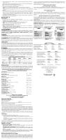
Inserting and Removing SDS Max Accessories Fig. 6 - hammer drill
 |
View all Dewalt D25603K manuals
Add to My Manuals
Save this manual to your list of manuals |
Page 2 highlights
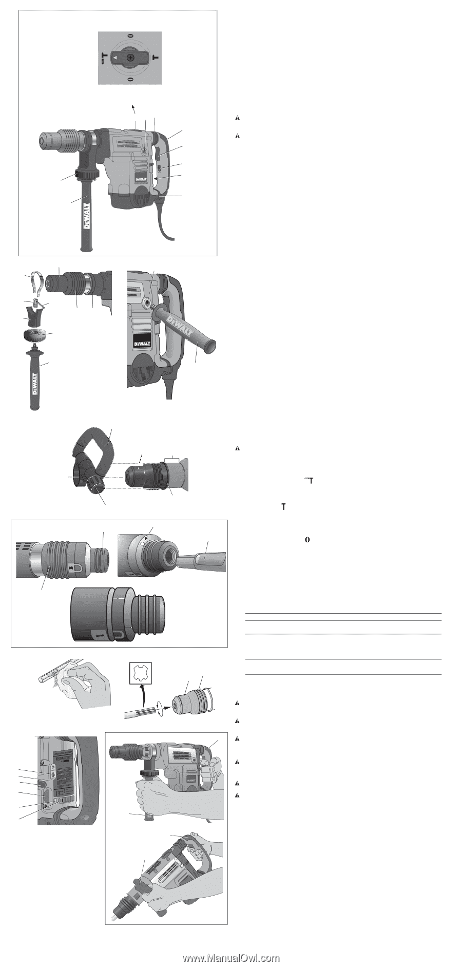
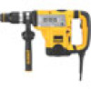
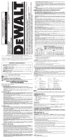
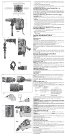
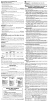
FIG. 1 CHISEL BIT ADJUSTMENT MODE MODE DE RÉGLAGE DU TRÉPAN ORDINAIRE MODO DE AJUSTE DE LA BROCA DE CINCEL HAMMERDRILLING MODE MODE DE MARTEAU PERFORATEUR MODO TALADRO PERCUTOR CHIPPING MODE MODE DE BURINAGE MODO CINCEL H C CHISEL BIT ADJUSTMENT MODE MODE DE RÉGLAGE DU TRÉPAN ORDINAIRE MODO DE AJUSTE DE LA BROCA DE CINCEL E FI D A B G E D25603 FIG. 2 M K N O P L J H FIG. 3 I C C FIG. 4 Q D25831 D25851 M Z FIG. 5 L R M T S P FIG. 6 FIG. 7 U V Y G X W P M FIG. 8 D D25501 D25553 D25601 D25603 D25651 C D D25831 D25851 Q 2. Slide the D-shaped handle (Q) and assembly over the tool holder (M) and onto the collar (L) in the mounting area (Z). The correct position of the D-shaped handle (Q) is between head and middle of the tube. 3. Adjust the D-shaped handle to the desired angle. 4. Slide and rotate the D-shaped handle to the desired position. 5. Lock the D-shaped handle in place by securely tightening the knob (R) so that the D-shaped handle assembly will not rotate. SHOCKS Active Vibration Control® System (Fig. 1, 8) D25651, D25601, D25603, D25831, D25851 For best vibration control, hold the tool with one hand on the main handle (D) and the other hand on the side handle (C) or D-shaped handle (Q). Apply just enough pressure so the damping device on the main handle is approximately mid stroke. The hammer only needs enough pressure to engage the active vibration control. Applying too much pressure will not make the tool drill or chip faster and active vibration control will not engage. Inserting and Removing Spline Drive Accessories (Fig. 5) D25553, D25651, D25851 WARNING: Burn hazard. ALWAYS wear gloves when changing bits. Accessible metal parts on the tool and bits may get extremely hot during operation. Small bits of broken material may damage bare hands. WARNING: Do not attempt to tighten or loosen drill bits (or any other accessory) by gripping the front part of the chuck and turning the tool on. Damage to the chuck and personal injury may occur. 1. Insert the bit shank into the tool holder (M) as far as it will go. The groove on the chisel shank (S) must be aligned with the symbol (T) on the toolholder. If inserted correctly, the locking sleeve (P) moves back to the end position and shows a closed lock symbol. 2. Pull on the bit to be sure that it is properly locked. 3. If the chisel groove is not aligned with the symbol, or is not inserted to the complete depth the lock symbol remains open. To remove the bit, pull back the locking sleeve and pull the bit out. Inserting and Removing SDS Max Accessories (Fig. 6) D25501, D25601, D25603, D25831 1. Pull back the locking sleeve (P) and insert the bit shank. The bit shank must be clean. 2. Turn the bit slightly until the sleeve snaps back into position. 3. Ensure the bit is properly engaged. NOTE: The bit needs to move several centimeters in and out of the tool holder (M) when properly engaged. 4. To remove the bit, pull back the locking sleeve and pull the bit out. Two-Stage Clutch/E-ClutchTM (Fig. 7) NOTICE: Always turn the tool off before changing torque control settings or damage to tool may result. TWO-STAGE CLUTCH D25603, D25651 Clutch Setting 1 (U) is designed for most hammerdrilling applications and is designed to easily clutch out when the drill bit encounters re-bar or other foreign substances. Clutch Setting 2 (V) is designed for higher torque applications such as core-bits and deep hole hammerdrilling and is designed to clutch out at a higher torque threshold. Move the torque control lever (Y) to Clutch Setting 1 or 2 as needed for application. NOTE: Allow the motor housing to rotate a little while changing torque. NOTE: If it is not possible to select Clutch Setting 2, run the unit under load and try again. Each time the tool is plugged in, it will automatically default to Clutch Setting 1, the most sensitive setting. E-CLUTCH™ D25603 In addition, E-Clutch™ offers increased user comfort and safety through an on-board antirotation technology capable of detecting if the user loses control of the hammer. When a jam is detected, the torque and speed are reduced instantly. The red indicator LED (X) illuminates when the E-Clutch™ is engaged. Electronic Speed and Impact Control (Fig. 7) D25651, D25601, D25603, D25831, D25851 The electronic speed and impact control allows the use of smaller drill bits without the risk of bit breakage, hammerdrilling into light and brittle materials without shattering and optimal tool control for precise chipping. To set the control dial, turn the dial (G) to the desired level. The higher the number, the greater the speed and impact energy. Dial settings make the tool extremely adaptable for many different applications. The required setting depends on the bit size and hardness of material being drilled. Mode Selector (Fig. 1) NOTICE: Never change the mode while the unit is running. Tool must come to a complete stop before activating the mode selector button or damage to the tool may result. CAUTION: Do not change to hammerdrill mode with chisel bit in tool holder. Personal injury and damage to tool may result. The D25501, D25553, D25601 and D25603, D25651 use two operating modes. To select the required operating mode, rotate the mode selector (F) until the arrow points to the hammerdrilling or the chipping icon. The D25831 and D25851 use only the chipping mode. HAMMERDRILLING MODE ( ) D25501, D25553, D25601, D25603, D25651 The tool simultaneously rotates and impacts the work. This mode is appropriate for all concrete and masonry operations. CHIPPING MODE ( ) D25831, D25851 The spindle lock is engaged during chipping mode so the tool impacts the work without rotating. This mode is appropriate for light chipping, chiseling and demolition applications. NOTE: In chipping mode, the hammerdrill can also be used as a lever to free a jammed drill bit. CHISEL BIT ADJUSTMENT ( ) Turn the mode selector to one of the chisel bit adjustment icons to adjust the chisel to the desired position. There are multiple positions to set the angle of the chisel. After finding the desired position, slightly maneuver the chisel bit back and forth to ensure the chisel is properly engaged. Indicator Lights (Fig. 1, 7) The yellow brush wear indicator LED (W) lights up when the carbon brushes are nearly worn out indicating that the tool needs servicing within the next 8 hours of use. The red indicator LED (X) lights up if the lock-on slider (B) and/or E-Clutch™ is engaged in any mode except the chipping mode. The red indicator LED (X) starts to flash if there is a fault with the tool or the brushes have completely worn out (refer to Repairs under Maintenance). INDICATOR DIAGNOSIS OFF Tool is functioning normally SOLUTION Follow all warnings and instructions when operating tool SOLID Perform and protect control has been activated With tool properly supported, release trigger; the tool will function normally when the trigger is depressed again and the indicator light will go out FLASHING Perform and protect control is Take the tool to an authorized malfunctioning DEWALT repair agent. NOTE: If the tool power is insufficient for normal hammering and if the LED does not flash repeatedly after cycling the trigger, take the tool to an authorized DEWALT repair center. OPERATION WARNING: To reduce the risk of injury, turn unit off and disconnect it from power source before installing and removing accessories, before adjusting or when making repairs. An accidental start-up can cause injury. WARNING: To reduce the risk of personal injury, ALWAYS ensure workpiece is anchored or clamped firmly. If hammerdrilling thin material, use a wood "back-up" block to prevent damage to the material. WARNING: To reduce the risk of personal injury, ALWAYS operate the tool with the side handle properly installed and securely tightened. Failure to do so may result in the side handle slipping during tool operation and subsequent loss of control. Hold tool with both hands to maximize control. WARNING: Drill may stall if overloaded causing a sudden twist. Always expect the stall. Grip the drill firmly with both hands to control the twisting action and avoid injury. Proper Hand Position (Fig. 8) WARNING: To reduce the risk of serious personal injury, ALWAYS use proper hand position as shown. WARNING: To reduce the risk of serious personal injury, ALWAYS hold securely in anticipation of a sudden reaction. Proper hand position requires one hand on the side handle (C) or D-shaped handle (Q), with the other hand on the main handle (D). NOTE: Operating temperature of this tool is 19˚ to 104˚ F (-7 to +40˚ C). Using the tool outside of this temperature range will decrease the life of the tool. Trigger Switch (Fig. 1) D25501, D25553, D25601, D25603, D25651 To turn the tool on, depress the trigger switch (A). To stop the tool, release the trigger switch. In chipping mode only, lock the trigger switch on by pushing the lock-on slider (B) upward while depressing the trigger switch. To deactivate the lock-on slider, depress the trigger switch once then release. The lock-on slider may only be activated in chipping mode. The machine will stop running when trying to engage the lock-on slider in hammerdrilling mode. The motor will stop if the lock-on slider is activated when changing from chisel mode into hammerdrilling mode. D25831, D25851 For continuous operation, move the toggle switch (A) to the on position. To stop continuous operation, move the toggle switch to the off position. SOFT START FEATURE The soft start feature allows you to build up speed slowly, thus preventing the drill bit from walking off the intended hole position when starting. The soft start feature also reduces the immediate torque reaction transmitted to the gearing and the operator if the hammer is started with the drill bit in an existing hole.
-
 1
1 -
 2
2 -
 3
3 -
 4
4 -
 5
5 -
 6
6 -
 7
7
 |
 |