Dewalt D28114 Instruction Manual - Page 10
Components Fig. 1 - d28114n parts
 |
View all Dewalt D28114 manuals
Add to My Manuals
Save this manual to your list of manuals |
Page 10 highlights
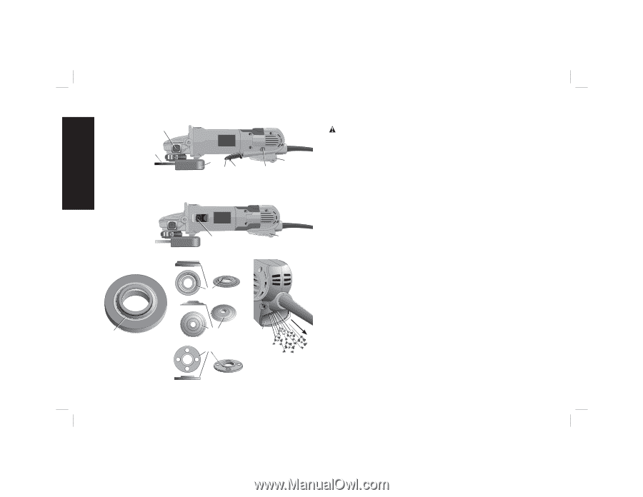
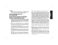
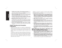
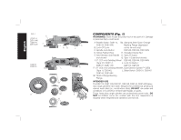
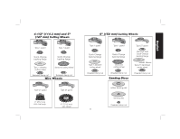
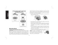
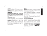
English FIG. 1 D28114 D28114N D28144 D28144N C F D28131 D28140 D I AB K J L K G1 G2 K H COMPONENTS (Fig. 1) WARNING: Never modify the power tool or any part of it. Damage or personal injury could result. A. Paddle Switch: D28114, G2. Stamped Steel Quick-Change D28144, D28144N Backing Flange (depressed B. Lock-Off Lever center wheels only): C. Spindle Lock Button D28140, D28144, D28144N D. Yellow Rubber Ring H. Threaded Clamp Nut E. Anti-Vibration Side Handle I1. Type 27 Guard (not shown) I2. Type 1 Guard (not shown): F. 5" (127 mm) Grinding Wheel D28140, D28144, D28144N (Type 27): D28114, J. Lock On Button: D28131, D28114N D28114, D28144 F1. 6" (152 mm) Grinding Wheel K. Dust Ejection System™ (DES) (Type 1): D28140, L. Slider Switch: D28131, D28140 D28144, D28144N G1.Quick-Change Backing Flange INTENDED USE The D28114, D28114N, D28131, D28140, D28144, D28144N heavyduty angle grinders have been designed for professional grinding at various work sites (i.e., construction sites). DO NOT use under wet conditions or in presence of flammable liquids or gases. These heavy-duty angle grinders are professional power tools. DO NOT let children come into contact with the tool. Supervision is required when inexperienced operators use this tool. 8
-
 1
1 -
2
-
3
-
4
-
 5
5 -
 6
6 -
 7
7 -
 8
8 -
 9
9 -
 10
10 -
 11
11 -
 12
12 -
 13
13 -
 14
14 -
 15
15 -
16
-
17
-
18
-
19
-
20
-
21
-
22
-
23
-
24
-
25
-
26
-
27
-
28
-
29
-
30
-
31
-
32
-
33
-
34
-
35
-
36
-
37
-
38
-
39
-
40
-
41
-
42
-
43
-
44
-
45
-
46
-
47
-
48
-
49
-
50
-
51
-
52
-
53
-
54
-
55
-
56
-
57
-
58
-
59
-
60
-
61
-
62
-
63
-
64
-
65
-
66
-
67
-
68
-
69
-
70
-
71
-
72
-
73
-
74
-
75
-
76
 |
 |