Dewalt D28114N Instruction Manual - Page 11
FEATURES, ASSEMBLY AND ADJUSTMENTS, Attaching Side Handle FIG. 2, Rotating the Gear Case - guard for
 |
View all Dewalt D28114N manuals
Add to My Manuals
Save this manual to your list of manuals |
Page 11 highlights
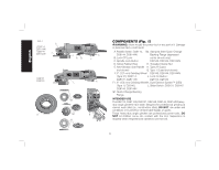
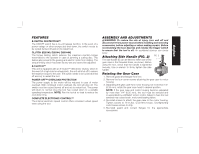
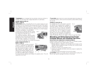
English FEATURES E-SWITCH PROTECTION™ The ON/OFF switch has a no-volt release function. In the event of a power outage or other unexpected shut down, the switch needs to be cycled (turned off and on) to restart tool. CLUTCH (D28140, D28144, D28144N) The torque limiting clutch reduces the maximum reaction torque transmitted to the operator in case of jamming a cutting disc. This feature also prevents the gearing and electric motor from stalling. The torque limiting clutch has been factory set and cannot be adjusted. E-CLUTCH™ This unit is equipped with an E-Clutch™ (Electronic Clutch), which in the event of a high-load or wheel pinch, the unit will shut off to reduce the reaction torque to the user. The switch needs to be cycled (turned off and on) to restart the tool. POWER-OFF™ OVERLOAD PROTECTION The power supply to the motor will be reduced in case of motor overload. With continued motor overload, the tool will shut off. The switch must be cycled (turned off and on) to restart tool. The power will return to normal once the tool has cooled down to a suitable operating temperature. NOTE: Run the tool at no load to reduce the cool down time. COMPLETE ELECTRONIC CONTROL™ The internal electronic speed control offers consistent wheel speed while using the tool. ASSEMBLY AND ADJUSTMENTS WARNING: To reduce the risk of injury, turn unit off and disconnect it from power source before installing and removing accessories, before adjusting or when making repairs. Before reconnecting the tool, depress and release the trigger switch to ensure that the tool is off. An accidental start-up can cause injury. Attaching Side Handle (FIG. 2) FIG. 2 The side handle (E) can be fitted to either side of the E gear case in the threaded holes, as shown. Before using the tool, check that the handle is tightened securely. Use a wrench to firmly tighten the side handle. Rotating the Gear Case 1. Remove guard and flanges from tool. 2. Remove the four corner screws attaching the gear case to motor housing. 3. Separating the gear case from motor housing not more than 1/4" (6.35 mm), rotate the gear case head to desired position. NOTE: If the gear case and motor housing become separated by more than 1/4" (6.35 mm), the tool must be serviced and re-assembled by a DEWALT service center. Failure to have the tool serviced may cause brush, motor and bearing failure. 4. Re-install screws to attach the gear case to the motor housing. Tighten screws to 18 in./lbs. (2.03 Nm) torque. Overtightening could cause screws to strip. 5. Re-install guard and correct flanges for the appropriate accessories. 9
-
 1
1 -
2
-
3
-
4
-
5
-
 6
6 -
 7
7 -
 8
8 -
 9
9 -
 10
10 -
 11
11 -
 12
12 -
 13
13 -
 14
14 -
 15
15 -
 16
16 -
17
-
18
-
19
-
20
-
21
-
22
-
23
-
24
-
25
-
26
-
27
-
28
-
29
-
30
-
31
-
32
-
33
-
34
-
35
-
36
-
37
-
38
-
39
-
40
-
41
-
42
-
43
-
44
-
45
-
46
-
47
-
48
-
49
-
50
-
51
-
52
-
53
-
54
-
55
-
56
-
57
-
58
-
59
-
60
-
61
-
62
-
63
-
64
-
65
-
66
-
67
-
68
-
69
-
70
-
71
-
72
-
73
-
74
-
75
-
76
 |
 |