Dewalt D28494S Instruction Manual - Page 14
Important Information About, Guards, Mounting And Removing Hubbed Wheels, Mounting Non-hubbed Wheels - d28494 w
 |
View all Dewalt D28494S manuals
Add to My Manuals
Save this manual to your list of manuals |
Page 14 highlights
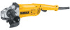
399080-02 rev 11/15/02 10:13 AM Page 10 English IMPORTANT INFORMATION ABOUT GUARDS Guards must be used with all grinding wheels, sanding flap discs, wire brushes and wire wheels. The tool may be used without a guard only when sanding with conventional sanding GRINDING WHEEL SURFACE discs. DEWALT models D28493, D28494, D28474, D28499 are provided with a guard intended for use with depressed center wheels GUARD LIP (Type 27), and hubbed grinding wheels (Type 27). The same guard is designed for use with sanding flap discs, wire brushes and wire wheels. Grinding and cutting with wheels other than Type 27 and 29 require different accessory guards not included with the tool. Mounting instructions for these accessory guards are included in the accessory package. CAUTION: When using a grinding wheel with a Type 27, 28, or 29 guard, be sure that the bottom surface of the grinding wheel is inside the the guard lip. CAUTION: DEWALT model D28497 Angle Sander may only be used for grinding by using appropriate accessory guard. 1. Open the guard latch (H), and align the lugs with slots on the gear case H cover. Position the guard facing backward, as shown. 4. Close the guard latch to secure the guard on the gear case. You should be unable to rotate the guard by hand when the latch is closed. Do not operate the grinder with a loose guard or the clamp lever in open position. 5. To remove the guard, follow the procedure above in reverse order. NOTE: The guard is pre-adjusted to the diameter of the gear case hub at the factory. If, after a period of time, the guard becomes loose, tighten the adjusting screw (I) with clamp in the closed position. I CAUTION: Do not tighten the adjusting screw with the clamp lever in open position. Undetectable damage to the guard or the mounting hub may result. MOUNTING AND REMOVING HUBBED WHEELS Hubbed wheels install directly on the 5/8" - 11 threaded spindle. 1. Thread the wheel on the spindle by hand, seating the wheel against the soft mount. 2. Depress the spindle lock button and use a wrench to tighten the hub of the wheel. 3. Reverse the above procedure to remove the wheel. 2. Push the guard down until the guard lugs engage and rotate freely in the groove on the gear case hub. CAUTION: Failure to properly seat the wheel against the soft mount before turning the tool on may result in damage to the tool or the wheel. 3. With the guard latch open, rotate the guard into the desired working position that provides maximum protection to the user as shown. MOUNTING NON-HUBBED WHEELS Depressed center, Type 27 grinding wheels must be used with available accessory flanges. See the chart on pages 5-7 of this manual for more information. 10
-
 1
1 -
2
-
3
-
4
-
5
-
6
-
7
-
8
-
 9
9 -
 10
10 -
 11
11 -
 12
12 -
 13
13 -
 14
14 -
 15
15 -
 16
16 -
 17
17 -
 18
18 -
 19
19 -
20
-
21
-
22
-
23
-
24
-
25
-
26
-
27
-
28
-
29
-
30
-
31
-
32
-
33
-
34
-
35
-
36
-
37
-
38
-
39
-
40
-
41
-
42
-
43
-
44
-
45
-
46
-
47
-
48
-
49
-
50
-
51
-
52
-
53
-
54
-
55
-
56
-
57
 |
 |
