Dewalt D28770 Instruction Manual - Page 2
Adjustments, OPERATION, Motor, Trigger Switch, Cutting - band saw
 |
View all Dewalt D28770 manuals
Add to My Manuals
Save this manual to your list of manuals |
Page 2 highlights
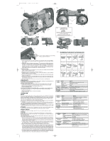
624781-00,D28770 4/15/04 4:24 PM Page 2 FIG. 1 C A P B J I H FIG 4 Q DDIDRBIIRELRLCAEAELDCTCLAIETCAOHIMOINÓONENDJAEDE LOOSEN DESSERRER AFLOJE F1 G O FIG. 5 F2 E FIG. 2 K D D M N E L FIG. 3 BLADE DIRECTION DIRECTION DE LA LAME DIRECCIÓN DE LA HOJA POSITION OF TEETH ON LEFT SIDE OF MACHINE POSITION DES DENTS DU CÔTÉ GAUCHE, SUR LE CÔTÉ DE LA MACHINE POSICIÓN DE LOS DIENTES SOBRE LADO IZQUIERDO DEL COSTADO DE LA MÁQUINA FIG. 6 FIG. 7 A J L FIG. 8 D E R PROPER FILL LEVEL / NIVEAU DE REMPLISSAGE APPROPRIÉ / NIVEL DE LLENADO CORRECTO FIG. 9 RECOMMENDED CUTTING POSITIONS / POSITIONS DE COUPE RECOMMANDÉES / POSICIONES DE CORTE RECOMENDADAS YES / OUI / SÍ NO / NON / NO YES / OUI / SÍ NO / NON / NO 4. Inspect the guide rollers (F1, F2) and remove any large chips which may be lodged in them. Lodged chips can prevent rotation of the guide rollers and cause flat spots on the guide rollers. 5. Rubber tires (N) are mounted on the pulleys (L). The rubber tires should be inspected for looseness or damage when changing the blade. Wipe any chips from the rubber tires on the pulleys. This will extend tire life and keep the blade from slipping. If any looseness or damage occurs, the tool should be brought to an authorized DEWALT service center for repair or replacement as soon as possible. Continued use of the tool with loose or damaged rubber tires will cause unstable travel of the band saw blade. TO INSTALL BLADE 1. Position the blade so that the teeth are on the bottom and angled toward the material guide, as shown in Figures 1 and 3. 2. Slip the blade into the guide rollers, as shown in Figure 4. 3. Holding the blade in the guide rollers, place it around both pulleys (L) and through the material guide (E), as shown in Figure 5. 4. Make sure that the blade is fully inserted into the guide rollers and positioned squarely against the rubber tires. 5. Gently turn the saw over so that the pulleys rest on your work bench or table and rotate the blade tension lever (H) counterclockwise until it stops. Make sure the teeth face away from the bandsaw (Fig. 1, 3). 6. Turn the saw on and off a few times to ensure that the blade is seated properly. Adjustments CAUTION: Turn off and unplug the tool before making any adjustments or removing/installing attachments or accessories. MATERIAL GUIDE ADJUSTMENT To support large workpieces, the material guide should be lowered following these steps: 1. Loosen the two M6 screws (Q), shown in Figure 1, with the Allen wrench provided. 2. Move the material guide (E) to the desired position (Fig 5). 3. Securely tighten M6 screws. LOCATION ADJUSTMENT OF GUIDE ROLLERS - for straighter cuts of smaller pieces For straight cuts on smaller pieces, adjust the guide rollers using the following steps: 1. Loosen 14mm bolt (G). 2. Move the front guide roller (F1) closer to the material. 3. Tighten 14mm bolt. OPERATION Motor Be sure your power supply agrees with the voltage marked on the nameplate. 120 Volts AC 60Hz means alternating current only. Voltage decrease of more than 10% will cause loss of power and overheating. All DEWALT tools are factory-tested. If this tool does not operate, check the power supply line for blown fuses and the plug and receptacle for proper contact. There are certain applications for which this tool was designed. This band saw is designed to cut various types of material up to 4-3/4" (120.7 mm) diameter or 4-3/4" (120.7 mm) x 4-3/4" (120.7 mm) rectangular shape at 90˚. WARNING: Thoroughly remove any oil or grease from the workpiece before securing in a vise or other clamping device. If the workpiece is not secure, it may come loose during the cutting and/or cause breakage, which may result in serious personal injury. WARNING: Never connect the power tool unless the available AC power is of the same voltage as that specified on the nameplate of the tool. Never connect this power tool to a DC power source. WARNING: If the power cord is connected to the power source with the trigger switch turned ON the power tool will start suddenly and could cause a serious accident. Trigger Switch To start the tool, squeeze the trigger switch (C). To turn the tool off, release the switch. Cutting CAUTION: Refer to Figure 9 for recommended cutting positions for various materials. NOTE: Select and use a band saw blade that is most appropriate for the material being cut. See Blade Description. This portable band saw may be hung using the hang hook (K). Hang tool on a pipe vice or other suitable, stable structure. (Fig. 2) 1. Mount the material to be cut solidly in a vise or other clamping device. Never attempt to use this tool by resting it on a work surface and bringing the material to the tool. Always securely clamp the workpiece and bring the tool to the workpiece, securely holding the tool with two hands as shown in Figure 6. 2. If additional light is needed, a sight light (B) can be activated using the sight light switch (P) as shown in Figure 1. If replacement is required, return to an authorized service center or other qualified service personnel, always using identical replacement parts. 3. Bring the material guide (E) into contact with the workpiece. Turn the saw ON. 4. When saw reaches desired rotation speed, slowly and gently tilt the main body of the tool to bring the band saw blade into contact with the workpiece. Do not apply additional pressure in excess of the weight of the main body of the tool. Carefully avoid bringing the band saw blade suddenly and heavily into contact with the upper surface of the workpiece. This will cause serious damage to the band saw blade. To obtain maximum service life of the band saw blade, ensure there is no sudden impact at the beginning of the cutting operation. 5. As shown in Figures 6 and 7, straight cutting can be accomplished by keeping the band saw blade aligned with the side surface of the motor housing. Any twisting or cocking of the blade will cause the cut to go offline and decrease the life of the blade. YES / OUI / SÍ NO / NON / NO YES / OUI / SÍ NO / NON / NO YES / OUI / SÍ NO / NON / NO YES / OUI / SÍ NO / NON / NO Item Model D28770 Motor Type Protected type, series commutator motor Power source single-phase, AC 60Hz Voltage 120 volts Full-load current 6 amp Band Saw Dimensions 1/2" x 44-7/8" x .020" (12.5 mm x 1140 mm x .5 mm) Blade Peripheral speed 80 - 280 ft/min (25-85 m/min) Max. Cutting Pipe outer dimensions 4-3/4" (120,7 mm) Dimensions Stock 4-3/4" x 4-3/4" (120,7 mm x 120,7 mm) Net Weight 15 lbs. (6.8 kg) Cord 3 conductor type captive cable 8.0 ft. (2.4 m) Article Moteur Lame de scie à ruban Dimensions maximales de la coupe Poids net Cordon Modèle D28770 Type Type protégé, série moteur à collecteur Circuit d'alimentation électrique monophasé, c.a., 60Hz Tension 120 volts Courant de pleine charge 6 A Dimensions 12,5 mm x 1 140 mm x 0,5 mm (1/2 po x 44-7/8 po x .020 po) Vitesse périphérique 25 à 85 m/min (80 à 280 pi/min) Dimensions externes du tuyau 120,7 mm (4-3/4 po) Matériau à couper 120,7 mm x 120,7 mm (4-3/4 po x 4-3/4 po) 6,8 kg (15 lb) Fiche à 3 broches et à 3 conducteurs de 2,4 m (8,0 pi)) Artículo Motor Hoja de la sierra de banda Dimensiones máximas de corte Peso neto Cable Modelo Tipo Fuente de alimentación Voltaje Corriente a plena carga Dimensiones Velocidad periférica Dimensiones exteriores de tubería Material a cortar D28770 Motor conmutador en serie, tipo protegido CA 60 Hz, monofásica 120 voltios 6 amperios 12,5 mm x 1 140 mm x 0,5 mm (1/2 pulg. x 44-7/8 pulg. x .020 pulg.) 25 - 85 m/min (80 - 280 pies/min) 120,7 mm (4-3/4 pulg.) 120,7 x 120,7 mm (4-3/4 x 4-3/4 pulg.) 6,8 kg (15 lb.) Cable cautivo de 3 conductores, de 2,4 m (8,0 pies) de largo
-
 1
1 -
 2
2 -
 3
3 -
 4
4 -
 5
5 -
 6
6
 |
 |
