Dewalt DC385B Instruction Manual - Page 2
Cutting with Blade in Horizontal Position Fig. 7 - manual
 |
View all Dewalt DC385B manuals
Add to My Manuals
Save this manual to your list of manuals |
Page 2 highlights
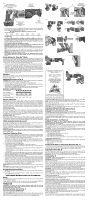
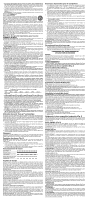
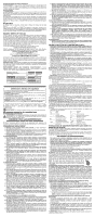
FIG. 1 LOCK-OFF BUTTON BOUTON DE VERROUILLAGE BOTÓN DE BLOQUEO EN OFF (APAGADO) HAND GRIP POIGNÉE EMPUÑADURA FIG. 2 FIG. 3 UNLOCKED B DÉVERROUILLÉ DESBLOQUEADO TRIGGER SWITCH GÂCHETTE CONMUTADOR TIPO GATILLO SHOE PATIN BASE METÁLICA least the minimum wire size. The following table shows the correct size to use depending on cord length and nameplate ampere rating. If in doubt, use the next heavier gauge. The smaller the gauge number, the heavier the cord. Recommended Minimum Wire Size for Extension Cords Total Length of Cord 25 ft. 50 ft. 75 ft. 100 ft. 125 ft. 150 ft. 175 ft. 7.6 m 15.2 m 22.9 m 30.5 m 38.1 m 45.7 m 53.3 m Wire Size AWG 18 18 16 16 14 14 12 • Do not place any object on top of charger or place the charger on a soft surface that might block the ventilation slots and result in excessive internal heat. Place the charger in a position away from any heat source. The charger is ventilated through slots in the top and the bottom of the housing. • Do not operate charger with damaged cord or plug. • Do not operate charger if it has received a sharp blow, been dropped, or otherwise damaged in any way. Take it to an authorized service center. • Do not disassemble charger; take it to an authorized service center when service or repair is required. Incorrect reassembly may result in a risk of electric shock, electrocution or fire. • Disconnect the charger from the outlet before attempting any cleaning. This will reduce the risk of electric shock. Removing the battery pack will not reduce this risk. • NEVER attempt to connect 2 chargers together. • The charger is designed to operate on standard 120V household electrical power. Do not attempt to use it on any other voltage. This does not apply to the vehicular charger. Using Automatic Tune-Up™ Mode The automatic Tune-Up™ Mode equalizes or balances the individual cells in the battery pack allowing it to function at peak capacity. Battery packs should be tuned up weekly or after 10 charge/discharge cycles or whenever the pack no longer delivers the same amount of work. To use the automatic Tune-Up™, place the battery pack in the charger and leave it for at least 8 hours. The charger will cycle through the following modes. 1. The red light will blink continuously indicating that the 1-hour charge cycle has started. 2. When the 1-hour charge cycle is complete, the light will stay on continuously and will no longer blink. This indicates that the pack is fully charged and can be used at this time. 3. If the pack is left in the charger after the initial 1-hour charge, the charger will begin the Automatic Tune-Up™ mode. This mode continues up to 8 hours or until the individual cells in the battery pack are equalized. The battery pack is ready for use and can be removed at any time during the Automatic Tune-Up™ mode. 4. Once the Automatic Tune-Up™ mode is complete, the charger will begin a maintenance charge; the red indicator will remain lit. Chargers Your tool uses a DEWALT 14,4 or 18 volt charger. Be sure to read all safety instructions before using your charger. Consult the chart at the end of this manual for compatibility of chargers and battery packs. Charging Procedure (Fig. 2) DANGER: Electrocution hazard. 120 volts present at charging terminals. Do not probe with conductive objects. Danger of electric shock or electrocution. 1. Plug the charger into an appropriate outlet before inserting battery pack. 2. Insert the battery pack into the charger. The red (charging) light will blink continuously indicating that the charging process has started. 3. The completion of charge will be indicated by the red light remaining ON continuously. The pack is fully charged and may be used at this time or left in the charger. Indicator Light Operation FIG. 4 FIG. 6 FIG. 7 C FIG. 9 FIG. 11 ROCK TOOL UP TO NORMAL CUTTING POSITION AFTER BLADE HAS CUT THROUGH MATERIAL PIVOTER L'OUTIL EN POSITION NORMALE DE COUPE UNE FOIS QUE LA LAME A TRAVERSÉ LE MATÉRIAU. BALANCEE LA HERRAMIENTA HACIA ARRIBA HASTA ALCANZAR LA POSICIÓN NORMAL DE CORTE LUEGO DE QUE LA HOJA ATRAVIESE EL MATERIAL FIG. 5 LOCKED VERROUILLÉ BLOQUEADO A FIG. 8 FIG. 10 FIG. 12 Charge Indicators Some chargers are designed to detect certain problems that can arise with battery packs. Problems are indicated by the red light flashing at a fast rate. If this occurs, re-insert battery pack into the charger. If the problem persists, try a different battery pack to determine if the charger is OK. If the new pack charges correctly, then the original pack is defective and should be returned to a service center or other collection site for recycling. If the new battery pack elicits the same trouble indication as the original, have the charger tested at an authorized service center. HOT/COLD PACK DELAY Some chargers have a Hot/Cold Pack Delay feature: when the charger detects a battery that is hot, it automatically starts a Hot Pack Delay, suspending charging until the battery has cooled. After the battery has cooled, the charger automatically switches to the Pack Charging mode. This feature ensures maximum battery life. The red light flashes long, then short while in the Hot Pack Delay mode. PROBLEM POWER LINE Some chargers have a Problem Power Line indicator. When the charger is used with some portable power sources such as generators or sources that convert DC to AC, the charger may temporarily suspend operation, flashing the red light with two fast blinks followed by a pause. This indicates the power source is out of limits. LEAVING THE BATTERY PACK IN THE CHARGER The charger and battery pack can be left connected with the red light glowing indefinitely. The charger will keep the battery pack fresh and fully charged. NOTE: A battery pack will slowly lose its charge when kept out of the charger. If the battery pack has not been kept on maintenance charge, it may need to be recharged before use. A battery pack may also slowly lose its charge if left in a charger that is not plugged into an appropriate AC source. WEAK BATTERY PACKS: Chargers can also detect a weak battery pack. Such batteries are still usable but should not be expected to perform as much work. The charger will indicate to replace battery pack. Important Charging Notes 1. Longest life and best performance can be obtained if the battery pack is charged when the air temperature is between 65°F and 75°F (18°- 24°C). DO NOT charge the battery pack in an air temperature below +40°F (+4.5°C), or above +105°F (+40.5°C). This is important and will prevent serious damage to the battery pack. 2. The charger and battery pack may become warm to touch while charging. This is a normal condition, and does not indicate a problem. To facilitate the cooling of the battery pack after use, avoid placing the charger or battery pack in a warm environment such as in a metal shed, or an uninsulated trailer. 3. If the battery pack does not charge properly: a. Check current at receptacle by plugging in a lamp or other appliance; b. Check to see if receptacle is connected to a light switch which turns power off when you turn out the lights; c. Move charger and battery pack to a location where the surrounding air temperature is approximately 65°F - 75°F (18°- 24°C); d. If charging problems persist, take the tool, battery pack and charger to your local service center. 4. The battery pack should be recharged when it fails to produce sufficient power on jobs which were easily done previously. DO NOT CONTINUE to use under these conditions. Follow the charging procedure. You may also charge a partially used pack whenever you desire with no adverse affect on the battery pack. 5. Under certain conditions, with the charger plugged into the power supply, the exposed charging contacts inside the charger can be shorted by foreign material. Foreign materials of a conductive nature such as, but not limited to, grinding dust, metal chips, steel wool, aluminum foil, or any buildup of metallic particles should be kept away from charger cavities. Always unplug the charger from the power supply when there is no battery pack in the cavity. Unplug charger before attempting to clean. 6. Do not freeze or immerse charger in water or any other liquid. WARNING: Shock hazard. Don't allow any liquid to get inside charger. Electric shock may result. CAUTION: Never attempt to open the battery pack for any reason. If the plastic housing of the battery pack breaks or cracks, return to a service center for recycling. Storage Recommendations 1. The best storage place is one that is cool and dry away from direct sunlight and excess heat or cold. 2. Long storage will not harm the battery pack or charger. Under proper conditions, they can be stored for 5 years or more. SAVE THESE INSTRUCTIONS FOR FUTURE USE Motor Your DEWALT tool is powered by a DEWALT-built motor. Be sure your power supply agrees with the nameplate markings. Voltage decrease of more than 10% will cause loss of power and overheating. All DEWALT tools are factory tested; if this tool does not operate, check your battery pack. OPERATION WARNING: To reduce the risk of serious personal injury, turn tool off and disconnect tool from power source before making any adjustments or removing/ installing attachments or accessories. Switch (Variable Speed) (Fig. 3) LOCK-OFF BUTTON AND TRIGGER SWITCH Your saw is equipped with a lock-off button (B). To lock the trigger switch, press the lock-off button as shown in Figure 3. Always lock the trigger switch (A) when carrying or storing the tool to eliminate unintentional starting. The lock-off button is colored red to indicate when the switch is in its unlocked position. STARTING POSITION FOR POCKET CUTTING POSITION DE DÉPART POUR COUPE INTERNE POSICIÓN INICIAL PARA CORTES CENTRALES To unlock the trigger switch, press the lock-off button as shown in Figure 3. Pull the trigger switch to turn the motor ON. Releasing the trigger switch turns the motor OFF. NOTE: This tool has no provision to lock the switch in the ON position, and should never be locked ON by any other means. The variable speed trigger switch will give you added versatility. The further the trigger is depressed the higher the speed of the saw. CAUTION: Use of very slow speed is recommended only for beginning a cut. Prolonged use at very slow speed may damage your saw. Installing and Removing the Battery Pack NOTE: Make sure your battery pack is fully charged. WARNING: Lock trigger switch before removing or installing battery. To install the battery pack into the tool handle, align the base of the tool with the notch inside the tool's handle and slide the battery pack firmly into the handle until you hear the lock snap into place as shown in Figure 4. To remove the battery pack from the tool, press the release buttons and firmly pull the battery pack out of the tool handle. Insert it into the charger as described in the charger manual. Blade Installation and Removal WARNING: To reduce the risk of serious personal injury, turn tool off and disconnect tool from power source before making any adjustments or removing/ installing attachments or accessories. Different blade lengths are available. Use the appropriate blade for the application. The blade should be longer than 3-1/2" and should extend past the shoe and the thickness of the workpiece during the cut. Do not use jigsaw blades with this tool. WARNING: Cut hazard. Blade breakage may occur if the blade does not extend past the shoe and the workpiece during the cut (Fig. 5). Increased risk of personal injury, as well as damage to the shoe and workpiece may result. TO INSTALL BLADE INTO SAW 1. Open blade clamp release lever (C) up (Fig. 6). 2. Insert blade shank from the front. 3. Close blade clamp release lever down. 4. Note blade can be installed upside-down to assist in flush-to cutting, see Figure 10. TO REMOVE BLADE FROM SAW CAUTION: Burn hazard. Do not touch the the blade immediately after use. Contact with the blade may result in personal injury. 1. Open up blade clamp release lever. 2. Remove blade. Cutting with Blade in Horizontal Position (Fig. 7) Your saw may or may not be equipped with a horizontal blade clamp. Installing a blade in the horizontal orientation allows cutting close to floors, walls or ceilings where limited clearance is available. Ensure that the shoe is pressed against the framing to avoid kickback. Adjustable Shoe (Fig. 8) Your saw may or may not come with an adjustable shoe. The shoe will adjust to limit the depth of cut. Hold the saw with the underside facing up. Push the button on the hand grip and slide the shoe out to one of the three settings and release the button. CAUTION: Cut hazard. To prevent loss of control, never use tool without shoe. Cutting (Fig. 9) WARNING: Always use eye protection. All users and bystanders must wear eye protection that conforms to ANSI Z87.1. WARNING: Exercise extra caution when cutting towards operator. Always hold saw firmly with both hands while cutting. Before cutting any type of material, be sure it is firmly anchored or clamped to prevent slipping. Place blade lightly against work to be cut, switch on saw motor and allow it to obtain maximum speed before applying pressure. Whenever possible, the saw shoe must be held firmly against the material being cut. This will prevent the saw from jumping or vibrating and minimize blade breakage. Any cut which puts pressure on the blade such as angle or scroll cuts increase potential for vibration, kickback, and blade breakage. WARNING: Use extra caution when cutting overhead and pay particular attention to overhead wires which may be hidden from view. Anticipate the path of falling branches and debris ahead of time. WARNING: Inspect work site for hidden gas pipes, water pipes, or electrical wires before making blind or plunge cuts. Failure to do so may result in explosion, property damage, electric shock, and/or serious personal injury. FLUSH-TO CUTTING (FIG. 10) The compact design of the saw motor housing and spindle housing permits extremely close cutting to floors, corners and other difficult areas. POCKET/PLUNGE CUTTING - WOOD ONLY (FIG. 11) The initial step in pocket cutting is to measure the surface area to be cut and mark clearly with a pencil, chalk or scriber. Use the appropriate blade for the application. The blade should be longer than 3-1/2" and should extend past the shoe and the thickness of the workpiece during the cut. Insert blade in blade clamp. Next, tip the saw backward until the back edge of the shoe is resting on the work surface and the blade clears the work surface. Now switch motor on, always permitting blade to attain maximum speed. Grip handle steadily and begin a slow, deliberate upward swing with the handle of the saw. Blade will begin to feed into material. Always be sure blade is completely through material before continuing with pocket cut. NOTE: In areas where blade visibility is limited, use the edge of the saw shoe as a guide. Lines for any given cut should be extended beyond edge of cut to be made. METAL CUTTING (FIG. 12) This unit has different metal cutting capacities depending upon type of blade used and the metal to be cut. Use a finer blade for ferrous metals and a coarse blade for non-ferrous
-
 1
1 -
 2
2 -
 3
3 -
 4
4 -
 5
5 -
 6
6 -
 7
7
 |
 |
