Dewalt DC668KA Instruction Manual - Page 2
Installing and Removing the Battery Pack - tools
 |
View all Dewalt DC668KA manuals
Add to My Manuals
Save this manual to your list of manuals |
Page 2 highlights
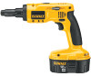
CAUTION: Burn hazard. To reduce the risk of injury, charge only DEWALT rechargeable batteries. Other types of batteries may burst causing personal injury and damage. CAUTION: Under certain conditions, with the charger plugged in to the power supply, the exposed charging contacts inside the charger can be shorted by foreign material. Foreign materials of a conductive nature such as, but not limited to, steel wool, aluminum foil, or any buildup of metallic particles should be kept away from charger cavities. Always unplug the charger from the power supply when there is no battery pack in the cavity. Unplug charger before attempting to clean. • DO NOT attempt to charge the battery pack with any chargers other than the ones in this manual. The charger and battery pack are specifically designed to work together. • These chargers are not intended for any uses other than charging DEWALT recharge- able batteries. Any other uses may result in risk of fire, electric shock or electrocution. • Do not expose charger to rain or snow. • Pull by plug rather than cord when disconnecting charger. This will reduce risk of damage to electric plug and cord. • Make sure that cord is located so that it will not be stepped on, tripped over, or other- wise subjected to damage or stress. • Do not use an extension cord unless it is absolutely necessary. Use of improper extension cord could result in risk of fire, electric shock, or electrocution. • An extension cord must have adequate wire size (AWG or American Wire Gauge) for safety. The smaller the gauge number of the wire, the greater the capacity of the cable, that is 16 gauge has more capacity than 18 gauge. When using more than one extension to make up the total length, be sure each individual extension contains at least the minimum wire size. • Do not place any object on top of charger or place the charger on a soft surface that might block the ventilation slots and result in excessive internal heat. Place the charger in a position away from any heat source. The charger is ventilated through slots in the top and the bottom of the housing. • Do not operate charger with damaged cord or plug - have them replaced immediately. • Do not operate charger if it has received a sharp blow, been dropped, or otherwise damaged in any way. Take it to an authorized service center. • Do not disassemble charger; take it to an authorized service center when service or repair is required. Incorrect reassembly may result in a risk of electric shock, electrocution or fire. • Disconnect the charger from the outlet before attempting any cleaning. This will reduce the risk of electric shock. Removing the battery pack will not reduce this risk. • NEVER attempt to connect 2 chargers together. • The charger is designed to operate on standard household electrical power (120 Volts). Do not attempt to use it on any other voltage. This does not apply to the vehicular charger. Using Automatic Tune-Up™ Mode The automatic Tune-Up™ Mode equalizes or balances the individual cells in the battery pack allowing it to function at peak capacity. Battery packs should be tuned up weekly or after 10 charge/discharge cycles or whenever the pack no longer delivers the same amount of work. To use the automatic Tune-Up™, place the battery pack in the charger and leave it for at least 8 hours. The charger will cycle through the following modes. 1. The red light will blink continuously indicating that the 1-hour charge cycle has started. 2. When the 1-hour charge cycle is complete, the light will stay on continuously and will no longer blink. This indicates that the pack is fully charged and can be used at this time. 3. If the pack is left in the charger after the initial 1-hour charge, the charger will begin the Automatic Tune-Up mode. This mode continues up to 8 hours or until the individual cells in the battery pack are equalized. The battery pack is ready for use and can be removed at any time during the Tune-Up mode. 4. Once the Automatic Tune Up mode is complete, the charger will begin a maintenance charge; the red indicator will remain lit. SAVE THESE INSTRUCTIONS FOR FUTURE USE Chargers Your battery can be charged in DEWALT 1 Hour Chargers, 15 Minute Chargers or Vehicular 12 Volt Charger. Be sure to read all safety instructions before using your charger. Consult the chart at the end of this manual for compatibility of chargers and battery packs. Charging Procedure DANGER: Electrocution hazard. 120 volts are present at charging terminals. Do not probe with conductive objects. 1. Plug the charger into an appropriate outlet as shown in Figure 1. 2. Insert the battery pack into the charger. The red (charging) light will blink continuously indicating that the charging process has started. 3. The completion of charge will be indicated by the red light remaining ON continuously. The pack is fully charged and may be used at this time or left in the charger. Indicator Light Operation Charge Indicators Some chargers are designed to detect certain problems that can arise with battery packs. Problems are indicated by the red light flashing at a fast rate. If this occurs, re-insert battery pack into the charger. If the problem persists, try a different battery pack to determine if the charger is OK. If the new pack charges correctly, then the original pack is defective and should be returned to a service center or other collection site for recycling. If the new battery pack elicits the same trouble indication as the original, have the charger tested at an authorized service center. HOT/COLD PACK DELAY Some chargers have a Hot/Cold Pack Delay feature: when the charger detects a battery that is hot, it automatically starts a Hot Pack Delay, suspending charging until the battery has cooled. After the battery has cooled, the charger automatically switches to the Pack Charging mode. This feature ensures maximum battery life. The red light flashes long, then short while in the Hot Pack Delay mode. PROBLEM POWER LINE Some chargers have a Problem Power Line indicator. When the charger is used with some portable power sources such as generators or sources that convert DC to AC, the charger may temporarily suspend operation, flashing the red light with two fast blinks followed by a pause. This indicates the power source is out of limits. LEAVING THE BATTERY PACK IN THE CHARGER The charger and battery pack can be left connected with the red light glowing indefinitely. The charger will keep the battery pack fresh and fully charged. NOTE: A battery pack will slowly lose its charge when kept out of the charger. If the battery pack has not been kept on maintenance charge, it may need to be recharged before use. A battery pack may also slowly lose its charge if left in a charger that is not plugged into an appropriate AC source. WEAK BATTERY PACKS: Chargers can also detect a weak battery. Such batteries are still usable but should not be expected to perform as much work. In such cases, about 10 seconds after battery insertion, the charger will beep rapidly 8 times to indicate a weak battery condition. The charger will then go on to charge the battery to the highest capacity possible. Important Charging Notes 1. Longest life and best performance can be obtained if the battery pack is charged when the air temperature is between 65°F and 75°F (18°- 24°C). DO NOT charge the battery pack in an air temperature below +40°F (+4.5°C), or above +105°F (+40.5°C). This is important and will prevent serious damage to the battery pack. 2. The charger and battery pack may become warm to touch while charging. This is a normal condition, and does not indicate a problem. To facilitate the cooling of the battery pack after use, avoid placing the charger or battery pack in a warm environment such as in a metal shed, or an uninsulated trailer. 3. If the battery pack does not charge properly: a. Check current at receptacle by plugging in a lamp or other appliance b. Check to see if receptacle is connected to a light switch which turns power off when you turn out the lights. c. Move charger and battery pack to a location where the surrounding air temperature is approximately 65°F - 75°F (18°- 24°C). d. If charging problems persist, take the tool, battery pack and charger to your local service center. 4. The battery pack should be recharged when it fails to produce sufficient power on jobs which were easily done previously. DO NOT CONTINUE to use under these conditions. Follow the charging procedure. You may also charge a partially used pack whenever you desire with no adverse affect on the battery pack. 5. Under certain conditions, with the charger plugged into the power supply, the exposed charging contacts inside the charger can be shorted by foreign material. Foreign materials of a conductive nature such as, but not limited to, steel wool, aluminum foil, or any buildup of metallic particles should be kept away from charger cavities. Always unplug the charger from the power supply when there is no battery pack in the cavity. Unplug charger before attempting to clean. 6. Do not freeze or immerse charger in water or any other liquid. FIG. 1 FIG. 2 FIG. 3 B A FIG. 4 FIG. 5 C VERSA-CLUTCH™ WARNING: Shock hazard. Do not allow any liquid to get inside charger. CAUTION: Never attempt to open the battery pack for any reason. If the plastic housing of the battery pack breaks or cracks, return to a service center for recycling. OPERATION Installing and Removing the Battery Pack NOTE: Make sure your battery pack is fully charged. CAUTION: Lock trigger switch before removing or installing battery. To install the battery pack into the tool handle, align the base of the tool with the notch inside the tool's handle and slide the battery pack firmly into the handle until you hear the lock snap into place (Fig. 2). To remove the battery pack from the tool, press the release buttons and firmly pull the battery pack out of the tool handle. Insert it into the charger as described in the charger manual. Variable Speed Switch (Fig. 3) To turn the tool ON, squeeze the trigger switch (A). To turn the tool OFF release the trigger. Your tool is equipped with a variable speed switch which enables you to select the best speed for a particular application. The farther you squeeze the trigger, the faster the tool will operate. For maximum tool life, use variable speed only for starting fasteners. Forward/Reverse Control Button (Fig. 3, 4) A forward/reverse control button (B) determines the direction of the tool and also serves as a lock-off button. To select forward rotation, release the trigger switch (A) and depress the forward/reverse control button (B) on the right side of the tool. To select reverse, depress the forward/reverse control button on the left side of the tool. The center position of the control button locks the tool in the OFF position. When changing the position of the forward/reverse control button, be sure the trigger is released. Dead Spindle Action All DEWALT light gauge screwdrivers provide a dead front spindle to permit fasteners to be located in the driving accessory. Clutches are held apart by light spring pressure, permitting the drilling clutch to rotate without turning the driven clutch and accessory. When sufficient forward pressure is applied to the unit, the clutches engage and rotate the spindle and accessories. Accessory Assembly (Fig. 5) The 1/4" hex drive ball lock chuck is a quick-release system. To install a bit, pull out on the spindle collar (C), insert the bit of choice and release. The tool is locked in place. To remove the bit, pull out the spindle collar and take out the bit. Versa Clutch™ Feature (Fig. 5) External adjustment of all Versa Clutch™ units for a wide range of fastener sizes is fast and easy as follows: 1. Pull forward, then rotate collar in increase direction (stamped on adjustment collar) to increase the amount of clutch engagement and torque output. 2. Maximum rotation of the collar in the increase direction results in full clutch engagement and maximum torque output and fastener capacity. Collar and adjustable stop will not screw off clutch housing. 3. Test drive a fastener into a scrap piece to check proper fastener seating. It is normal after a period of use to require a slightly different collar setting due to wear on the clutch faces. NOTE: With Versa Clutch™, the operator has the ability to "override" clutch ratchet if a fastener hits a wood knot, variable hardness in steel work pieces or incorrect pilot holes. Increased operator pressure will usually cause the clutches to pick-up and continue to seat the fastener. Further, a quick twist of the collar will change the clutch setting to overcome most driving difficulties and will provide for immediate change in torque output giving the operator the option to drive a wide range of fastener sizes. Driving Self-Drilling Fasteners DEWALT screwdrivers are designed to safely deliver self-drilling screws into light gauge metal including drywall studs, heat ducting and sheet metal assembly without pre-drilling a pilot hole. 1. Select proper length self drilling screw to ensure complete fastening into the metal stud or sheet metal. 2. More pressure can be applied to the bit if the screwdriver is gripped by sliding the thumb and index finger along the side of the tool near the top. Actuate the trigger with middle and/or fourth finger. DEWALT has designed recesses along the top sides of your screwdriver to allow for a comfortable grip. 3. Avoid driving self-drilling fasteners into very heavy gauge steel without a drilled pilot hole. MAINTENANCE Cleaning CAUTION: Blow dirt and dust out of all air vents with dry air at least once a week. Wear safety glasses when performing this. Never use solvents or other harsh chemicals for cleaning the non-metallic parts of the tool. These chemicals may weaken the plastic materials used in these parts. Use a cloth dampened only with water and mild soap. Depth locator and adjustment collar should be removed and dust blown out of clutch area housing at least once a week. CHARGER CLEANING INSTRUCTIONS WARNING: Shock hazard. Disconnect the charger from the AC outlet before cleaning. Dirt and grease may be removed from the exterior of the charger using a cloth or soft non-metallic brush. Do not use water or any cleaning solutions. Lubrication All ball and needle bearings are factory lubricated for the life of the tool. Accessories Recommended accessories for use with your tool are available at extra cost from your local dealer or authorized service center. If you need assistance in locating any accessory, please contact DEWALT Industrial Tool Co., 701 East Joppa Road, Baltimore, MD 21286, call 1-800-4-DEWALT (1-800-433-9258) or visit our website www.dewalt.com. CAUTION: The use of any non-recommended accessory may be hazardous. Repairs To assure product SAFETY and RELIABILITY, repairs, maintenance and adjustment (including brush inspection and replacement) should be performed by a DEWALT factory service center, a DEWALT authorized service center or other qualified service personnel. Always use identical replacement parts. Three Year Limited Warranty DEWALT will repair, without charge, any defects due to faulty materials or workmanship for three years from the date of purchase. This warranty does not cover part failure due to normal wear or tool abuse. For further detail of warranty coverage and warranty repair information, visit www.dewalt.com or call 1-800-4-DEWALT (1-800-433-9258). This warranty does not apply to accessories or damage caused where repairs have been made or attempted by others. This
-
 1
1 -
 2
2 -
 3
3 -
 4
4 -
 5
5 -
 6
6 -
 7
7
 |
 |
