Dewalt DCD985L2 Instruction Manual - Page 15
Screwdriving Fig. 4, Hammerdrilling Fig. 5, Drilling Fig. 3 - model
 |
View all Dewalt DCD985L2 manuals
Add to My Manuals
Save this manual to your list of manuals |
Page 15 highlights
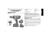
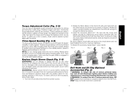
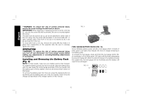
English NOTE: The fuel gauge is only an indication of the charge left on the battery pack. It does not indicate tool functionality and is subject to variation based on product components, temperature and end-user application. For more information regarding fuel gauge battery packs, please call 1-800-4-DEWALT (1-800-433-9258) or visit our website www.dewalt. com. Drilling (Fig. 3) NOTICE: If drilling thin material, use a wood "back-up" block to prevent damage to the material. 1. Select the desired speed/torque range using the gear shifter to match the speed and torque to the planned operation. Set the mode control collar to the drill symbol. 2. Use sharp drill bits only. For MASONRY, such as brick, cement, cinder block, etc., use carbide-tipped bits rated for percussion drilling. 3. Always apply pressure in a straight line with the bit. Use enough pressure to keep the drill bit biting, but do not push hard enough to stall the motor or deflect the bit. 4. Hold tool firmly with both hands to control the twisting action of the drill. If model is not equipped with side handle, grip drill with one hand on the handle and one hand on the battery pack. WARNING: Drill may stall if overloaded causing a sudden twist. Always expect the stall. Grip the drill firmly to control the twisting action and avoid injury. 5. IF DRILL STALLS, it is usually because it is being overloaded. RELEASE TRIGGER IMMEDIATELY, remove drill bit from work, and determine cause of stalling. DO NOT DEPRESS TRIGGER OFF AND ON IN AN ATTEMPT TO START A STALLED DRILL - THIS CAN DAMAGE THE DRILL. 6. To minimize stalling or breaking through the material, reduce pressure on drill and ease the bit through the last fractional part of the hole. 7. Keep the motor running when pulling the bit back out of a drilled hole. This will help prevent jamming. Screwdriving (Fig. 4) 1. Select the desired speed/torque range using the three-speed gear shifter (G) on the top of the tool to match the speed and torque to the planned application. Initially set the torque adjustment collar (E) at a lower setting to ensure the fastener is set to your specification. NOTE: Use the lowest torque setting required to seat the fastener at the desired depth. The lower the number, the lower the torque output. 2. Rotate the mode control collar (F) so the screw symbol is aligned with the arrow. 3. Make a few practice runs in scrap or unseen areas of the workpiece to determine the proper position of the torque adjustment collar. Reset the torque adjustment collar (E) to the appropriate number setting for the torque desired. 4. Always start with lower torque settings, then advance to higher torque settings to avoid damage to the workpiece or fastener. NOTE: The torque adjustment collar may be set to any number at any time. However, the torque adjustment collar is only engaged during screwdriving mode and not in drill and hammerdrill modes. Hammerdrilling (Fig. 5) 1. Select the desired speed/torque range using the gear shifter to match the speed and torque to the planned operation. Set the mode control collar to the hammer symbol. IMPORTANT: Use carbide-tipped or masonry bits rated for percussion drilling only. 13
-
 1
1 -
2
-
3
-
4
-
5
-
6
-
7
-
8
-
9
-
 10
10 -
 11
11 -
 12
12 -
 13
13 -
 14
14 -
 15
15 -
 16
16 -
 17
17 -
 18
18 -
 19
19 -
 20
20 -
21
-
22
-
23
-
24
-
25
-
26
-
27
-
28
-
29
-
30
-
31
-
32
-
33
-
34
-
35
-
36
-
37
-
38
-
39
-
40
-
41
-
42
-
43
-
44
-
45
-
46
-
47
-
48
-
49
-
50
-
51
-
52
-
53
-
54
-
55
-
56
 |
 |