Dewalt DCF889B User Guide - Page 12
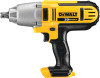
Variable Speed Trigger Switch fig. 1, Forward/Reverse Control Button, fig. 1, Worklight fig. 1, Anvil - lowes
 |
View all Dewalt DCF889B manuals
Add to My Manuals
Save this manual to your list of manuals |
Page 12 highlights
ENGLISH WARNING: To reduce the risk of serious personal injury, ALWAYS hold securely in anticipation of a sudden reaction. Proper hand position requires one hand on the main handle (d). Variable Speed Trigger Switch (fig. 1) To turn the tool on, squeeze the trigger switch (a). To turn the tool off, release the trigger switch. Your tool is equipped with a brake. The anvil will stop when the trigger switch is fully released. The variable speed switch enables you to select the best speed for a particular application. The more you squeeze the trigger, the faster the tool will operate. For maximum tool life, use variable speed only for starting holes or fasteners. NOTE: Continuous use in variable speed range is not recommended. It may damage the switch and should be avoided. Forward/Reverse Control Button (fig. 1) A forward/reverse control button (b) determines the direction of the tool and also serves as a lock-off button. To select forward rotation, release the trigger switch and depress the forward/reverse control button on the right side of the tool. To select reverse, release the trigger switch and depress the forward/reverse control button on the left side of the tool. The center position of the control button locks the tool in the off position. When changing the position of the control button, be sure the trigger is released. NOTE: The first time the tool is run after changing the direction of rotation, you may hear a click on start up. This is normal and does not indicate a problem. Worklight (fig. 1) There is a worklight (g) located above the trigger switch (a). The worklight is activated when the trigger switch is depressed. When the trigger is released, the worklight will stay illuminated for up to 20 seconds. NOTE: The worklight is for lighting the immediate work surface and is not intended to be used as a flashlight. Anvil (fig. 2) WARNING: Use only impact accessories. Non-impact accessories may break and cause a hazardous condition. Inspect accessory prior to use to ensure that it contains no cracks. CAUTION: Inspect anvils and detent pins prior to use. Missing or damaged items should be replaced before use. Place the switch in the locked off (center) position or remove battery pack before changing accessories. ANVIL WITH DETENT PIN (FIG. 2) To install an accessory on the anvil, align the hole in the side of the accessory with the detent pin (h) on the anvil (c). Press the accessory on until the detent pin engages in the hole. Depression of detent pin may be necessary to aid installation of accessory. To remove an accessory, depress the detent pin through the hole and pull the accessory off. Usage Your impact tool can generate the following maximum torque: Cat # Ft.-Lbs. In.-Lbs. Nm DCF889 300 3600 418 WARNING: Ensure fastener and/ or system will withstand the level of torque generated by the tool. Excessive torque may cause breakage and possible personal injury. 1. Place the accessory on the fastener head. Keep the tool pointed straight at the fastener. 2. Press switch to start operation. Release switch to stop operation. Always check torque with a torque wrench, as the fastening torque is affected by many factors including the following: • Voltage: Low voltage, due to a nearly discharged battery, will reduce fastening torque. • Accessory size: Failure to use the correct accessory size will cause a reduction in fastening torque. • Bolt size: Larger bolt diameters generally require higher fastening torque. Fastening torque will also vary according to length, grade, and torque coefficient. • Bolt: Ensure that all threads are free of rust and other debris to allow proper fastening torque. 36
-
 1
1 -
2
-
3
-
4
-
5
-
6
-
 7
7 -
 8
8 -
 9
9 -
 10
10 -
 11
11 -
 12
12 -
 13
13 -
 14
14
 |
 |
