Dewalt DCG412B Instruction Manual - Page 14
Save These Instructions, For Future Use, Components Fig. 2, 9, Assembly And Adjustments, Attaching
 |
View all Dewalt DCG412B manuals
Add to My Manuals
Save this manual to your list of manuals |
Page 14 highlights
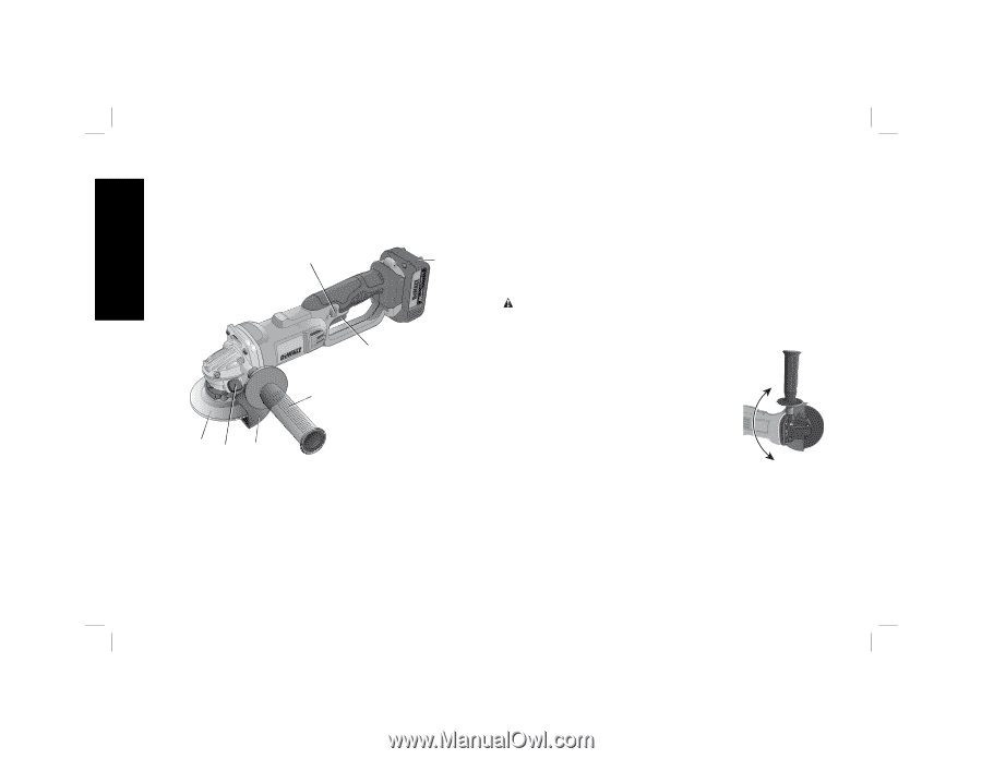
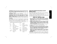
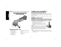
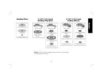
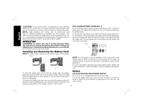
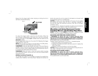
English NOTE: Battery packs should not be stored completely depleted of charge. The battery pack will need to be recharged before use. SAVE THESE INSTRUCTIONS FOR FUTURE USE FIG. 2 B J A E FC I Components (Fig. 2, 9) A. Trigger switch G. Unthreaded backing flange B. Lock-off button (Fig. 9) C. Spindle lock button H. Threaded clamp nut (Fig. 9) D. Spindle (Fig. 9) I. Guard E. Side handle J. Battery pack F. Abrasive wheel ASSEMBLY AND ADJUSTMENTS Attaching Side Handle (Fig. 2) The side handle (E) can be fitted to either side of the gear case in the threaded holes. Before using the tool, check that the handle is tightened securely. To improve user comfort, the gear case will rotate 90° for cutting operations. Rotating the Gear Case WARNING: To reduce the risk of serious personal injury, turn tool off and remove the battery pack before making any adjustments or removing/installing attachments or accessories. An accidental start-up can cause injury. 1. Remove the four corner screws attaching the FIG. 3 gear case to motor housing. 2. Without separating the gear case from motor housing, rotate the gear case head to desired position. NOTE: If the gear case and motor housing become separated by more than 1/8" (3.17 mm), the tool must be serviced and re-assembled by a DEWALT service center. Failure to have the tool serviced may cause brush, motor and bearing failure. 3. Reinstall screws to attach the gear case to the motor housing. Tighten screws to 20 in.-lbs. torque. Overtightening could cause screws to strip. 12
-
 1
1 -
2
-
3
-
4
-
5
-
6
-
7
-
8
-
 9
9 -
 10
10 -
 11
11 -
 12
12 -
 13
13 -
 14
14 -
 15
15 -
 16
16 -
 17
17 -
 18
18 -
 19
19 -
20
-
21
-
22
-
23
-
24
-
25
-
26
-
27
-
28
-
29
-
30
-
31
-
32
-
33
-
34
-
35
-
36
-
37
-
38
-
39
-
40
-
41
-
42
-
43
-
44
-
45
-
46
-
47
-
48
-
49
-
50
-
51
-
52
-
53
-
54
-
55
-
56
-
57
-
58
-
59
-
60
-
61
-
62
-
63
-
64
-
65
-
66
-
67
-
68
-
69
-
70
-
71
-
72
-
73
-
74
-
75
-
76
-
77
-
78
-
79
-
80
-
81
-
82
-
83
-
84
-
85
-
86
-
87
-
88
 |
 |