Dewalt DCH253B Instruction Manual - Page 12
Worklight Fig. 5 DCH253 only, Trigger Switch Fig. 2, Mode Selector Fig. 3, Forward/Reverse Control - dch253 problems
 |
View all Dewalt DCH253B manuals
Add to My Manuals
Save this manual to your list of manuals |
Page 12 highlights
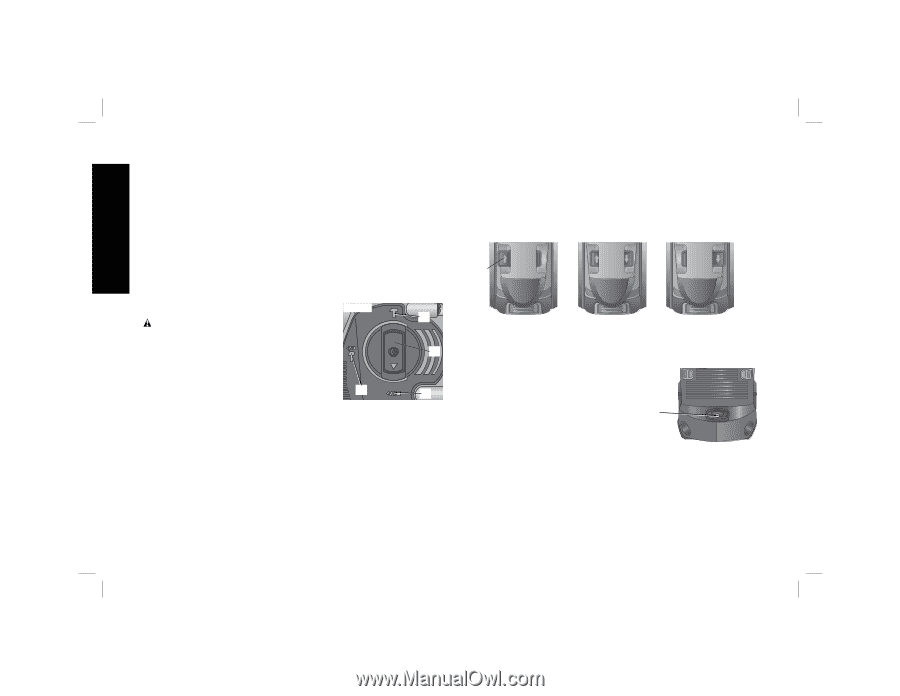
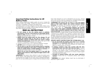
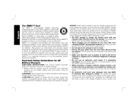
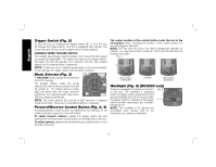
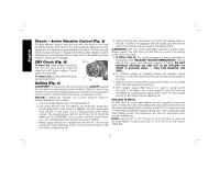
English Trigger Switch (Fig. 2) To turn the tool on, squeeze the trigger switch (B). To turn the tool off, release the trigger switch. Your tool is equipped with a brake. The chuck will stop as soon as the trigger switch is fully released. VARIABLE SPEED TRIGGER SWITCH The variable speed trigger switch enables you to select the best speed for a particular application. The farther you squeeze the trigger switch, the faster the tool will operate. For maximum tool life, use variable speed only for starting holes or fasteners. NOTE: Continuous use in variable speed range is not recommended. It may damage the trigger switch and should be avoided. Mode Selector (Fig. 3) FIG. 3 CAUTION: Never change the mode while K the unit is running. For straight drilling, rotate the mode selector (D) until the arrow points to the drill D bit symbol (I). For rotary hammer mode, align the arrow with the rotary hammer symbol (J). For chipping mode, align arrow J I with the chipping symbol (K). NOTE: The mode selector (D) must be in drill, hammer or chipping mode at all times. There are no operable positions in between. Forward/Reverse Control Button (Fig. 2, 4) A forward/reverse control button (C) determines the direction of bit rotation and also serves as a lock-off button. To select forward rotation, release the trigger switch (B) and depress the forward/reverse control button on the right side of the tool. To select reverse, depress the forward/reverse control button on the left side of the tool. The center position of the control button locks the tool in the off position. When changing the position of the control button, be sure the trigger is released. NOTE: The first time the tool is run after changing the direction of rotation, you may hear a click on start up. This is normal and does not indicate a problem. FIG. 4 C UNLOCKED, FORWARD LOCKED UNLOCKED, REVERSE Worklight (Fig. 5) (DCH253 only) There is a worklight (F) located on the front of the tool. The worklight is activated when the trigger switch is depressed, and will automatically turn off 20 seconds after the trigger switch is released. If the trigger switch remains depressed, the worklight will remain on. FIG. 5 F NOTE: The worklight is for lighting the immediate work surface and is not intended to be used as a flashlight. 10
-
 1
1 -
2
-
3
-
4
-
5
-
6
-
 7
7 -
 8
8 -
 9
9 -
 10
10 -
 11
11 -
 12
12 -
 13
13 -
 14
14 -
 15
15 -
 16
16 -
 17
17 -
18
-
19
-
20
-
21
-
22
-
23
-
24
-
25
-
26
-
27
-
28
-
29
-
30
-
31
-
32
-
33
-
34
-
35
-
36
-
37
-
38
-
39
-
40
-
41
-
42
-
43
-
44
-
45
-
46
-
47
-
48
-
49
-
50
-
51
-
52
-
53
-
54
-
55
-
56
 |
 |