Dewalt DW130V Instruction Manual - Page 2
Spade Handle Assembly Fig. 1 - type 1 parts
 |
View all Dewalt DW130V manuals
Add to My Manuals
Save this manual to your list of manuals |
Page 2 highlights
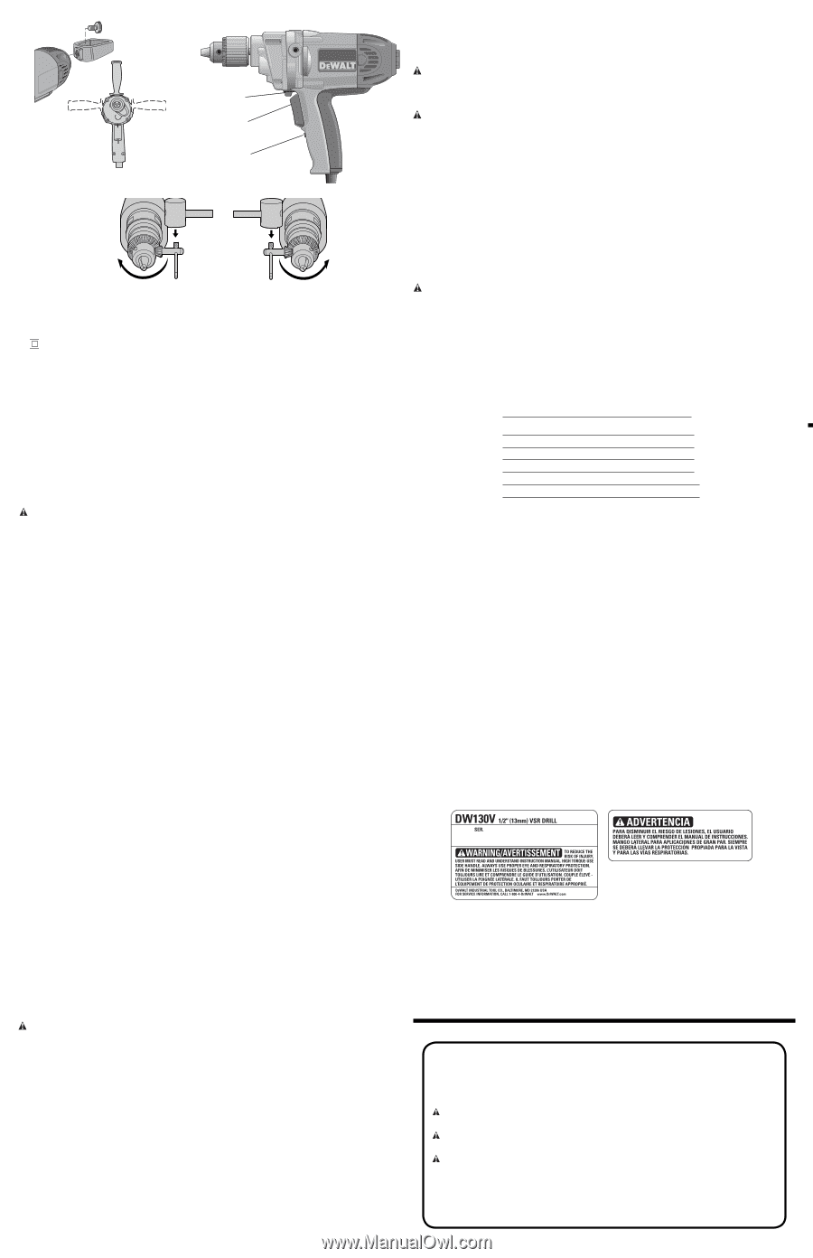
FIG. 1 FIG. 2 B A C FIG. 3 FIG. 4 Class II Construction double insulated) BPM beats per minute .../min............revolutions or reciprocation per minute SAVE THESE INSTRUCTIONS Motor Your DEWALT tool is powered by a DEWALT built motor. Be sure your power supply agrees with the nameplate marking. Voltage decrease of more than 10% will cause loss of power and overheating. All DEWALT tools are factory tested; if this tool does no operate, check the power supply. Spade Handle Assembly (Fig. 1) This spade handle can be attached either horizontally or vertically. Place the handle into the locating boss on the back of the drill and assemble with holding knob. Side Handle (Fig. 1) WARNING: To reduce the risk of personal injury, ALWAYS operate the tool with the side handle properly installed. Failure to do so may result in the side handle slipping during tool operation and subsequent loss of control. Hold tool with both hands to maximize control. The side handle can be placed in either side of the drill or the top of the drill according to operator preference and available working clearance. The spade handle can be temporarily removed if working clearance at rear of tool is limited. Always replace spade handle when possible. Switch (Fig. 2) To start the drill, depress the trigger switch; to stop the drill, release the trigger. A variable speed trigger switch (A) permits speed control-the farther the trigger is depressed, the higher the speed of the drill. NOTE: Use lower speeds for starting holes without a center punch, drilling in metal or plastics, driving screws or drilling ceramics. Higher speeds are better for drilling wood and composition boards and using abrasive and polishing accessories. The reversing lever (B) is used for withdrawing bits from tight holes and removing screws. It is located above the trigger switch. To reverse the motor, release the trigger switch FIRST and then push the lever to the right. After any reversing operations, return lever to forward position. The locking feature (C) is for use when the drill is mounted in a drill stand or otherwise firmly held...NOT BY HAND. Do not lock the switch "ON" when drilling by hand so that you can instantly release the trigger switch if the bit binds in the hole. Be sure to release the switch locking button before disconnecting the plug from the power supply. Failure to do so will cause the tool to start immediately the next time it is plugged in. Damage or injury could result. Chuck To insert bit, open chuck jaws by turning collar with fingers and insert shank of bit about 3/4" (19mm) into chuck. Tighten chuck collar by hand. Place chuck key in each of the three holes and tighten in clockwise direction. It's important to tighten chuck with all three holes. To release bit, turn chuck key counterclockwise in just one hole, then loosen the chuck by hand. Chuck Removal (Fig. 3, 4) 1. Place chuck key in chuck as shown in Figure 3. Using a wooden mallet or similar object, strike key sharply in a CLOCKWISE direction. This will loosen screw inside chuck. 2. Open chuck jaws fully. Insert screwdriver into front of chuck between jaws to engage screw head. Remove screw by turning clockwise (left-hand thread). 3. Place key in chuck as shown in Figure 4. Using a wooden mallet or similar object, strike key sharply in a COUNTERCLOCKWISE direction. This will loosen chuck so that it can be unscrewed by hand. Drilling 1. Use sharp drill bits only. For WOOD, use twist drill bits, spade bits, power auger bits, or hole saws. For METAL, use high-speed steel twist drill bits or hole saws. For MASONRY, such as brick, cement, cinder block etc., use carbide-tipped bits. 2. Be sure the material to be drilled is anchored or clamped firmly. If drilling thin material, use a wood "back-up" block to prevent damage to the material. 3. Always apply pressure in a straight line with the bit. Use enough pressure to keep drill biting, but do not push hard enough to stall the motor or deflect the bit. 4. Hold drill firmly to control the twisting action of the drill. Use side handle. CAUTION: Drill may stall if overloaded causing a sudden twist. Always expect the stall. Grip the drill firmly to control the twisting action and avoid injury. 5. IF DRILL STALLS, it is usually because it is being overloaded or improperly used. RELEASE TRIGGER IMMEDIATELY, remove drill bit from work, and determine cause of stalling. DO NOT CLICK TRIGGER OFF AND ON IN AN ATTEMPT TO START A STALLED DRILL - THIS CAN DAMAGE THE DRILL. 6. To minimize stalling on breaking through the material, reduce pressure on drill and ease the bit through the last fractional part of the hole. 7. Keep the motor running when pulling the bit back out of a drilled hole. This will help prevent jamming. DRILLING IN WOOD Holes in wood can be made with the same twist drills used for metal. These bits may overheat unless pulled out frequently to clear chips from the flutes. For larger holes, use spade bits, power auger bits, or hole saws. Work that is likely to splinter should be backed up with a block of wood. DRILLING IN METALS Use a cutting lubricant when drilling metals. The exceptions are cast iron and brass which should be drilled dry. The cutting lubricants that work best are sulphurised cutting oil or lard oil; bacon grease will also serve the purpose. DRILLING IN MASONRY Use carbide tipped masonry bits at low speeds. Keep even force on the drill but not so much that you crack the brittle materials. A smooth, even flow of dust indicates the proper drilling rate. MAINTENANCE WARNING: To reduce the risk of serious personal injury, turn tool off and disconnect tool from power source before making any adjustments or removing/installing attachments or accessories. Cleaning WARNING: Never use solvents or other harsh chemicals for cleaning the non-metallic parts of the tool. These chemicals may weaken the plastic materials used in these parts. Use a cloth dampened only with water and mild soap. Never let any liquid get inside the tool; never immerse any part of the tool into a liquid. Lubrication All bearings used are factory lubricated to last the life of the tool. All needle bearings used receive their lubrication from the grease in the gear case. Clean and relubricate gear case yearly or whenever servicing requires the gear case to be removed. Use type and quantity of grease shown on Parts Bulletin packed with your tool. Gear case is removed by removing the four screws from the front of the tool. If the chuck is too large to permit removal of the two top screws, see instructions for chuck removal. Motor Brushes This DEWALT tool uses an advanced brush system which automatically stops the tool when the brushes wear out. This prevents serious damage to the motor. Accessories WARNING: Since accessories, other than those offered by DEWALT, have not been tested with this product, use of such accessories with this tool could be hazardous. To reduce the risk of injury, only DEWALT, recommended accessories should be used with this product. Recommended accessories for use with your tool are available at extra cost from your local dealer or authorized service center. If you need assistance in locating any accessory, please contact DEWALT Industrial Tool Co., 701 East Joppa Road, Baltimore, MD 21286, call 1-800-4DEWALT (1-800-433-9258) or visit our website www.dewalt.com.. For safety in use, the following accessories should be used only in sizes up to the maximums shown in the table below. MAXIMUM RECOMMENDED CAPACITIES Drill Capacity 1/2" 13mm RPM 0-550 Steel twist bit Auger Self-feed Spade Wood holesaw Steel holesaw 1/2" 1-1/2" 3" 1-1/2" 5" 4" 13 mm 38 mm 76 mm 38 mm 127 mm 102 mm ACCESSORY MUST BE RATED FOR USE AT SPEED EQUAL TO OR HIGHER THAN NAMEPLATE RPM OF TOOL WITH WHICH IT IS BEING USED. Repairs To assure product SAFETY and RELIABILITY, repairs, maintenance and adjustment (including brush inspection and replacement) should be performed by authorized service centers or other qualified service organizations, always using identical replacement parts. Three Year Limited Warranty DEWALT will repair, without charge, any defects due to faulty materials or workmanship for three years from the date of purchase. This warranty does not cover part failure due to normal wear or tool abuse. For further detail of warranty coverage and warranty repair information, visit www.dewalt.com or call 1-800-4-DEWALT (1-800-433-9258). This warranty does not apply to accessories or damage caused where repairs have been made or attempted by others. This warranty gives you specific legal rights and you may have other rights which vary in certain states or provinces. In addition to the warranty, DEWALT tools are covered by our: 1 YEAR FREE SERVICE DEWALT will maintain the tool and replace worn parts caused by normal use, for free, any time during the first year after purchase. 90 DAY MONEY BACK GUARANTEE If you are not completely satisfied with the performance of your DEWALT Power Tool, Laser, or Nailer for any reason, you can return it within 90 days from the date of purchase with a receipt for a full refund - no questions asked. LATIN AMERICA: This warranty does not apply to products sold in Latin America. For products sold in Latin America, see country specific warranty information contained either in the packaging, call the local company or see website for warranty information. FREE WARNING LABEL REPLACEMENT: If your warning labels become illegible or are missing, call 1-800-4-DEWALT for a free replacement. Définitions : lignes directrices en matière de sécurité Les définitions ci-dessous décrivent le niveau de danger pour chaque mot-indicateur employé. Veuillez lire le mode d'emploi et porter une attention particulière à ces symboles. DANGER : indique une situation dangereuse imminente qui, si elle n'est pas évitée, causera la mort ou des blessures graves. AVERTISSEMENT : indique une situation potentiellement dangereuse qui, si elle n'est pas évitée, pourrait se solder par un décès ou des blessures graves. MISE EN GARDE : indique une situation potentiellement dangereuse qui, si elle n'est pas évitée pourrait se solder par des blessures mineures ou modérées. MISE EN GARDE : utilisé sans le symbole d'alerte à la sécurité, indique une situation potentiellement dangereuse qui, si elle n'est pas évitée pourrait se solder par des dommages à la propriété.
-
 1
1 -
 2
2 -
 3
3 -
 4
4 -
 5
5 -
 6
6
 |
 |