Dewalt DW297 Instruction Manual - Page 2
Les Directives Pour Un Usage UltÉrieur - impact wrench
 |
View all Dewalt DW297 manuals
Add to My Manuals
Save this manual to your list of manuals |
Page 2 highlights
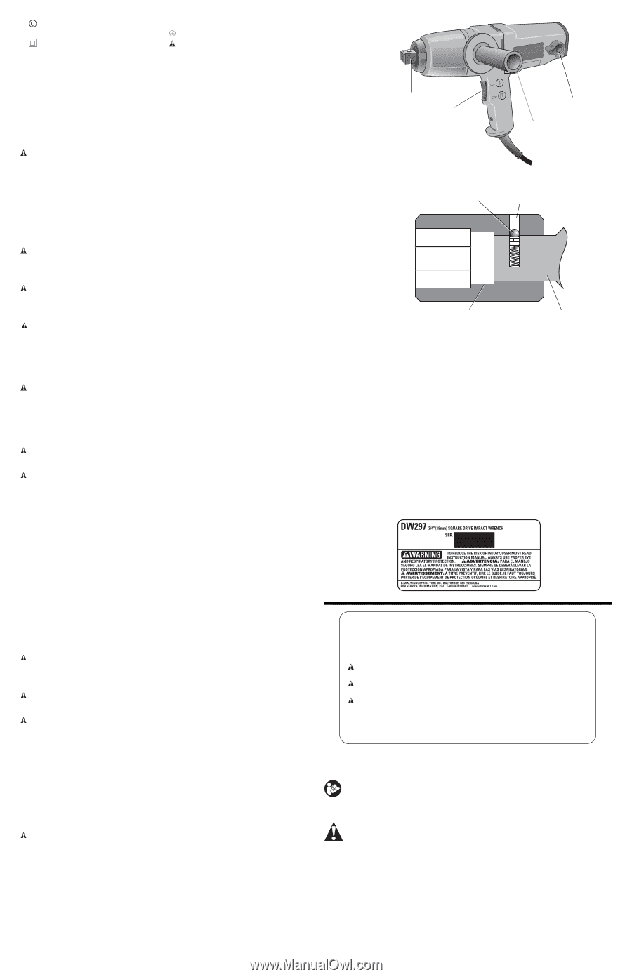
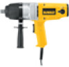
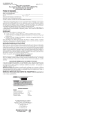
Class I Construction grounded) Class II Construction double insulated) .../min .........per minute IPM impacts per minute no no load speed earthing terminal safety alert symbol BPM beats per minute RPM revolutions per minute sfpm surface feet per minute SAVE THESE INSTRUCTIONS FOR FUTURE USE Motor Be sure your power supply agrees with the nameplate marking. Voltage decrease of more than 10% will cause loss of power and overheating. DEWALT tools are factory tested; if this tool does not operate, check power supply. COMPONENTS (Fig. 1) WARNING: Never modify the power tool or any part of it. Damage or personal injury could result. A. Anvil B. Switch C. Side handle D. Brush inspection cap Switch (Fig. 1) The switch (B) in this machine functions as a motor switch and a rotational direction selector switch. The lower part of the switch, marked with an R (right) will run the motor clockwise to tighten a bolt. The upper part of the switch, marked L (left) will run the motor counterclockwise to loosen the bolt. To stop the motor, release the switch. CAUTION: Be sure to turn the switch OFF and wait until the motor comes to a complete stop before changing direction of rotation. Switching direction of rotation while the motor is running may cause serious damage to the tool and the operator may loose control. ASSEMBLY AND ADJUSTMENTS WARNING: To reduce the risk of injury, turn unit off and disconnect it from power source before installing and removing accessories, before adjusting or when making repairs. An accidental start-up can cause injury. Mounting a Socket (Fig. 2) CAUTION: Use only impact sockets. Non-impact sockets may break and cause a hazardous condition. Inspect socket prior to use to ensure that it contains no cracks. To install a socket on the anvil (A), align the hole in the side of the socket (G) with the detent pin (E) on the anvil. Press the socket on until the detent pin engages in the hole (F). To remove a socket, depress the detent pin through the hole, using a small, pointed object, and pull the socket off. Side Handle (Fig. 1) WARNING: To reduce the risk of personal injury, ALWAYS operate the tool with the side handle properly installed. Failure to do so may result in the side handle slipping during tool operation and subsequent loss of control. Hold tool with both hands to maximize control. Always use side handle (C). The position of the side handle attached to the hammer case can be changed by unscrewing the handle (right hand threads). Relocate the handle to the desired position and reinstall. OPERATION WARNING: To reduce the risk of injury, turn unit off and disconnect it from power source before installing and removing accessories, before adjusting or when making repairs. An accidental start-up can cause injury. CAUTION: Ensure fastener and/or system will withstand the level of torque generated by the tool. Excessive torque may cause breakage and possible personal injury. Your impact tool generates 434 ft.-lbs. (60 kgm) output torque. 1. Place the socket on the fastener head. Keep the tool pointed straight at the fastener. 2. Press rocker switch to start operation. Always check torque with a torque wrench, as the fastening torque is affected by many factors including the following: • Voltage: Low voltage, due to generator or long extension cord, will reduce fastening torque. • Socket size: Failure to use the correct socket size will cause a reduction in fastening torque. • Bolt size: Larger bolt diameters generally require higher fastening torque. Fastening torque will also vary according to length, grade and torque coefficient. • Bolt: Ensure that all threads are free of rust and other debris to allow proper fastening torque. • Material: The type of material and surface finish of the material will affect fastening torque. • Fastening time: Longer fastening time results in increased fastening torque. Using a longer fastening time than recommended could cause the fasteners to be overstressed, stripped or damaged. Capacity Your 3/4" (19 mm) impact wrench uses sockets with 3/4" (19 mm) square drive ends. MAINTENANCE WARNING: To reduce the risk of injury, turn unit off and disconnect it from power source before installing and removing accessories, before adjusting or when making repairs. An accidental start-up can cause injury. Cleaning WARNING: Blow dirt and dust out of all air vents with clean, dry air at least once a week. To minimize the risk of eye injury, always wear ANSI Z87.1 approved eye protection when performing this. WARNING: Never use solvents or other harsh chemicals for cleaning the non-metallic parts of the tool. These chemicals may weaken the plastic materials used in these parts. Use a cloth dampened only with water and mild soap. Never let any liquid get inside the tool; never immerse any part of the tool into a liquid. Motor Brushes (Fig. 1) Be sure tool is unplugged before inspecting brushes. Carbon brushes should be regularly inspected for wear. To inspect brushes, unscrew the plastic brush inspection caps (D, located in the sides of the motor housing) and withdraw the spring and brush assemblies from the tool. Keep brushes clean and sliding freely in their guides. Carbon brushes have varying symbols stamped into them, and if the brush is worn down to the line closest to the spring, it must be replaced. New brush assemblies are available at extra cost from your local dealer or authorized service center. Accessories WARNING: Since accessories, other than those offered by DEWALT, have not been tested with this product, use of such accessories with this tool could be hazardous. To reduce the risk of injury, only DEWALT recommended accessories should be used with this product. Recommended accessories for use with your tool are available at extra cost from your local dealer or authorized service center. If you need assistance in locating any accessory, please contact DEWALT Industrial Tool Co., 701 East Joppa Road, Baltimore, MD 21286, call 1-800-4-DEWALT (1-800-433-9258) or visit our website: www.dewalt.com. Repairs To assure product SAFETY and RELIABILITY, repairs, maintenance and adjustment (including brush inspection and replacement) should be performed by a DEWALT factory service center, a DEWALT authorized service center or other qualified service personnel. Always use identical replacement parts. FIG. 1 FIG. 2 A B D C E F G A Three Year Limited Warranty DEWALT will repair, without charge, any defects due to faulty materials or workmanship for three years from the date of purchase. This warranty does not cover part failure due to normal wear or tool abuse. For further detail of warranty coverage and warranty repair information, visit www.dewalt.com or call 1-800-4-DEWALT (1-800-433-9258). This warranty does not apply to accessories or damage caused where repairs have been made or attempted by others. This warranty gives you specific legal rights and you may have other rights which vary in certain states or provinces. In addition to the warranty, DEWALT tools are covered by our: 1 YEAR FREE SERVICE DEWALT will maintain the tool and replace worn parts caused by normal use, for free, any time during the first year after purchase. 90 DAY MONEY BACK GUARANTEE If you are not completely satisfied with the performance of your DEWALT Power Tool, Laser, or Nailer for any reason, you can return it within 90 days from the date of purchase with a receipt for a full refund - no questions asked. LATIN AMERICA: This warranty does not apply to products sold in Latin America. For products sold in Latin America, see country specific warranty information contained in the packaging, call the local company or see website for warranty information. FREE WARNING LABEL REPLACEMENT: If your warning labels become illegible or are missing, call 1-800-4-DEWALT (1-800-433-9258) for a free replacement. Définitions : lignes directrices en matière de sécurité Les définitions ci-dessous décrivent le niveau de danger pour chaque mot-indicateur employé. Lire le mode d'emploi et porter une attention particulière à ces symboles. DANGER : indique une situation dangereuse imminente qui, si elle n'est pas évitée, entraînera la mort ou des blessures graves. AVERTISSEMENT : indique une situation potentiellement dangereuse qui, si elle n'est pas évitée, pourrait entraîner la mort ou des blessures graves. ATTENTION : indique une situation potentiellement dangereuse qui, si elle n'est pas évitée, pourrait entraîner des blessures légères ou modérées. AVIS : indique une pratique ne posant aucun risque de dommages corporels mais qui par contre, si rien n'est fait pour l'éviter, pourrait poser des risques de dommages matériels. POUR TOUTE QUESTION OU REMARQUE AU SUJET DE CET OUTIL OU DE TOUT AUTRE OUTIL DEWALT, COMPOSEZ LE NUMÉRO SANS FRAIS : 1-800-4-DEWALT (1-800-433-9258). AVERTISSEMENT : afin de réduire le risque de blessures, lire le mode d'emploi de l'outil. Avertissements de sécurité généraux pour les outils électriques AVERTISSEMENT ! Lire tous les avertissements de sécurité et toutes les directives. Le non-respect des avertissements et des directives pourrait se solder par un choc électrique, un incendie et/ou une blessure grave. CONSERVER TOUS LES AVERTISSEMENTS ET TOUTES LES DIRECTIVES POUR UN USAGE ULTÉRIEUR Le terme « outil électrique » cité dans les avertissements se rapporte à votre outil électrique à alimentation sur secteur (avec fil) ou par piles (sans fil). 1) SÉCURITÉ DU LIEU DE TRAVAIL a) Tenir l'aire de travail propre et bien éclairée. Les lieux encombrés ou sombres sont propices aux accidents. b) Ne pas faire fonctionner d'outils électriques dans un milieu déflagrant, tel qu'en présence de liquides, de gaz ou de poussières inflammables. Les outils électriques produisent des étincelles qui pourraient enflammer la poussière ou les vapeurs.
-
 1
1 -
 2
2 -
 3
3 -
 4
4 -
 5
5 -
 6
6
 |
 |