Dewalt DWC860W Instruction Manual - Page 2
To Install the Diamond Blade Fig. 1, 3
 |
View all Dewalt DWC860W manuals
Add to My Manuals
Save this manual to your list of manuals |
Page 2 highlights
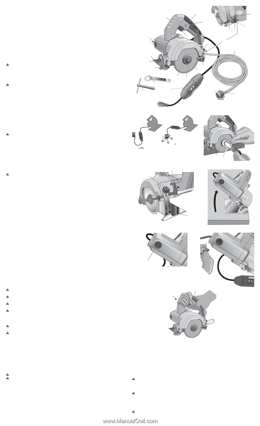
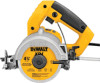
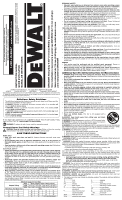
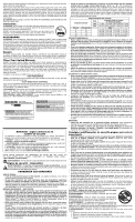
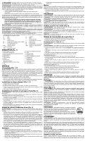
COMPONENTS (Fig. 1) A. GFCI on cord set B. On/Off Switch C. Lock-On button D. Diamond blade E. External flange F. Clamping screw G. Water tubing H. Tool inlet I. Water tubing adapter J. Water pressure regulator (5 psi) K. Screw L. Water nozzle M. Depth adjustment knob N. Shoe O. Water valve lever P. Cutting guide Q. Bevel adjustment knob R. Brush covers S. Brush assembly T. Front handle U. Main handle V. flange wrench W. T-handle wrench ASSEMBLY Switch (Fig. 1, 2) WARNING: To avoid the possibility of the appliance plug or receptacle getting wet, position the saw to one side of a wall mounted receptacle to prevent water from dipping onto the receptacle or plug. The user should arrange a "drip loop" in the cord connecting the saw to a receptacle (Fig. 2). The "drip loop" is that part of the cord below the level of the receptacle, or the connector if an extension cord is used, to prevent water traveling along the cord and coming in contact with the receptacle. CAUTION: Before plugging in tool, always check to see that the switch actuates properly and returns to the OFF position when released. 1. Depress and hold the switch (B) to start operation. 2. For continuous operation, press the lock-on button (C) and release the switch. To disengage the locking button, depress then release the switch. To Install the Diamond Blade (Fig. 1, 3) 1. Place saw on a stable surface. 2. Place blade (D) on spindle. 3. Using the flange wrench (V) provided, hold the external flange (E) 4. Turn the clamping screw (F) counterclockwise to tighten. Use the T-handle wrench (W) provided to secure tightly. 5. To remove the blade, reverse this procedure. Mounting the Wet Cut System (Fig. 1) WARNING: Do not use wet cut system unless tool is protected by a GFCI. This system minimizes airborne dust particles while improving cutting quality and blade life. 1. Loosen the depth adjustment knob (M) and pull shoe (N) to it's minimum depth of cut position. 2. Using a screwdriver, remove the screw (K) located next to the depth adjustment knob mounted to the casting. 3. Position the water valve assembly such that the hole in the water valve assembly aligns with the screw hole located in the casting and the forked water valve (L) straddles the blade. 4. Secure in place with screw. DO NOT overtighten the screw; this could damage the water valve assembly. Water Valve Assembly (Fig. 1) WARNING: Never use water valve assembly without a properly functioning pressure regulator. This could cause damage to the water tubing if excessive pressure builds up. 1. Never use the saw over head. When using water, limit cutting to the horizontal position to reduce the risk of water entering the tool. 2. Prior to using the tool with the water valve assembly, inspect water tubing (G) for holes cracks or other damage. Replace with identical replacement parts if a potential weakened or damaged area is found. Check connections at the tool inlet (H), water valve and adapter (I) for leaks. If the connection is loose or the tubing is relaxed around barbs, disconnect tubing, trim tubing back approximately 1" (25.4 mm), then reconnect tubing. Ensure that tubing is pushed all the way past the barb(s). Check to ensure tight connection. 3. When using the water kit, always use the water pressure regulator (J) provided. Firmly attach the regulator to the water source, but do not overtighten. Be sure to use the filter washer (inside regulator intake end) to prevent contaminates from clogging water jet ports. If regulator is lost or damaged, replace with identical replacement parts. Use of Extension Cords • Always plug extension cord into a GFCI receptacle. • Use only extension cords that are intended for outdoor use. These extension cords are identified by a marking "Acceptable for use with outdoor appliance; store indoors while not in use." • Use only extension cords having an electrical rating not less than the rating of the product. • Do not use damaged extension cords. Examine extension cord before using and replace if damaged. • Do not abuse extension cords and do not yank on any cord to disconnect. Motor Be sure your power supply agrees with the nameplate marking. Voltage decrease of more than 10% will cause loss of power and overheating. All DEWALT tools are factory tested; if this tool does not operate, check the power supply. • Keep cord away from heat and sharp edges. • Always disconnect the extension cord from the receptacle before disconnecting the product from the extension cord. OPERATION WARNING: Use the appropriate blade. Do not use cracked, damaged or excessively worn blades. Do not use to cut wood or metal. CAUTION: Wait for the blade to reach the maximum speed and use a slow even feed for proper cutting. CAUTION: The DWC860W should only be used on horizontal surfaces (see Water Valve Assembly). CAUTION: Use clamps or other practical way to secure and support the workpiece to a stable platform. Holding the work by hand or against your body is unstable and may lead to loss of control. Proper Hand Position (Fig. 8) WARNING: To reduce the risk of serious personal injury, Always use proper hand position as shown. WARNING: To reduce the risk of serious personal injury, always hold securely in anticipation of a sudden reaction. Proper hand position requires one hand on the main handle (U) and the other hand on the front handle (T) as shown. NOTE: Figure 8 shows the proper hand positon for a left-handed person. For a right-handed person, reverse the hand positions. Depth of Cut Adjustment (Fig. 4) 1. Loosen the depth adjustment knob (M) to release. 2. Move the shoe (N) up or down to desired position. 3. Tighten the depth adjustment knob. WET CUT METHOD (FIG. 1, 4) WARNING: Do not use wet cut system unless tool is protected by the GFCI. WARNING: To reduce the risk of electric shock, ensure water will not enter into your tool. Do not touch plug with wet hands. 1. Follow the instructions described under Mounting the Wet Cut System. 2. To regulate the water flow, open the water valve by pivoting the lever (O) away from the unit. 3. To close water valve, push the lever toward the unit. 3. Proceed as described below for straight or angled cuts. STRAIGHT CUTS (FIG. 1) 1. Using a marker or grease pencil, mark the area to be cut. 2. Place the shoe of the saw on the workpiece ensuring that the blade does not touch the workpiece. 3. Align the external part of the cutting guide (P) with the cut outline on the workpiece. 4. Turn the tool on and wait for the blade to reach its maximum velocity. FIG. 1 U O T C S R N Q P V W MK B M H G E F L D A J I FIG. 2 FIG. 3 FIG. 4 O M EF FIG. 5 FIG. 6 R N FIG. 7 S FIG. 8 U T 5. Move the tool slowly and evenly forward, following the cut line. ANGLED CUTS (FIG. 1, 5) 1. Using a marker or grease pencil, mark the area to be cut. 2. Release the bevel adjustment knob (Q) and move it to the desired angle. 3. After selecting the desired angle, tighten the knob to secure the shoe. 4. Align the internal part of the cutting guide (P) with the cut line on the workpiece. 5. Turn the tool on and wait for the blade to reach its maximum velocity. 6. Move the tool slowly and evenly forward, following the cut line. MAINTENANCE WARNING: To reduce the risk of serious personal injury, turn tool off and disconnect tool from power source before making any adjustments or removing/installing attachments or accessories. Cleaning WARNING: Never use solvents or other harsh chemicals for cleaning the non-metallic parts of the tool. These chemicals may weaken the plastic materials used in these parts. Use a cloth dampened only with water and mild soap. Never let any liquid get inside the tool; never immerse any part of the tool into a liquid. Brushes (Fig. 6, 7) WARNING: To reduce the risk of serious personal injury, turn tool off and disconnect tool from power source before making any adjustments or removing/installing attachments or accessories.
-
 1
1 -
 2
2 -
 3
3 -
 4
4 -
 5
5 -
 6
6 -
 7
7
 |
 |