Dewalt DWD460K Instruction Manual - Page 2
Forward/Reverse Button Fig. 1 - dwd460
 |
View all Dewalt DWD460K manuals
Add to My Manuals
Save this manual to your list of manuals |
Page 2 highlights
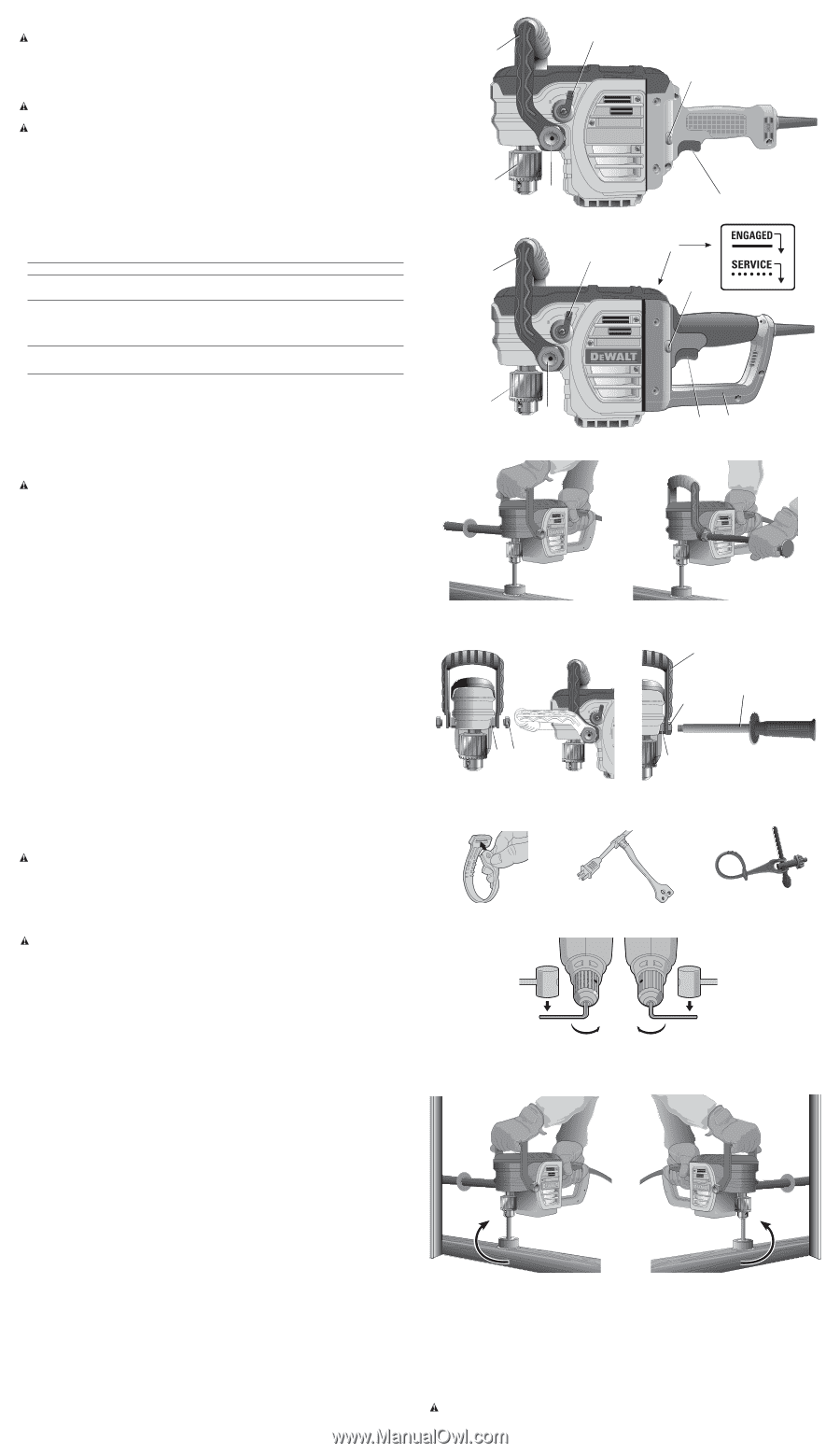
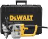
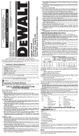
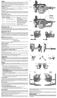
Torque WARNING: This is a high-torque drill. To reduce the risk of serious personal injury, ALWAYS hold tool firmly with both hands in the proper position for operation as shown. Torque is the twisting action the drill produces in regards to the rotating bit. As the drill bit meets resistance in the material being drilled, the motor responds by adjusting the output torque to meet the requirement up to the maximum capacity of the motor and gear system. BRACING THE TOOL (FIG. 2, 10) WARNING: To reduce the risk of serious personal injury, ALWAYS use proper hand position as shown in Figure 2. WARNING: To reduce the risk of serious personal injury, ALWAYS hold or brace the tool securely in anticipation of a sudden reaction. With hands in the proper hand position, brace the tool as shown in Figure 10. SLIP CLUTCH The DWD450 and DWD460 are each equipped with a slip clutch. The clutch is active when the low speed (1) is selected. When the bit or cutter bites into the workpiece, the clutch will slip and a ratcheting sound will be heard. Release the trigger. Continued clutching of the tool will reduce the life of this feature. BIND-UP CONTROL (DWD460) The DWD460 is equipped with bind-up control. This feature senses the motion of tool and reduces the motor torque to a manageable level if necessary. The bind-up control indicator (G) will illuminate to indicate status. INDICATOR DIAGNOSIS SOLUTION OFF Tool is functioning normal Follow all warnings and instructions when operating tool SOLID Bind up control has been activated With tool properly supported, release trigger; The tool will function normally when the trigger is depressed again and the indicator light will go out FLASHING Bind up control is malfunctioning Take the tool to an authorized DEWALT repair agent. NOTE: If tool power is insufficient for normal drilling and LED does not flash take tool to authorized DEWALT repair center. Bail Handle (Fig. 1, 3) A bail handle is provided for carrying the tool and for use as an additional handle. Assemble the bail handle in one of the positions shown in Figure 3. When changing the location of the bail handle from one position to the other, completely remove the two bail handle bolts (E) securing it. Flip the handle over and reinstall. Side Handle (Fig. 4) WARNING: To reduce the risk of personal injury, always operate the tool with the side handle properly installed and tightened. Failure to do so may result in the side handle slipping during tool operation and subsequent loss of control. Hold tool with both hands to maximize control. The two position side handle (I) can be assembled into either side of tool. Thread the side handle (I) into the bail handle bolt (E) or directly into threaded holes (J) on desired side. Tighten securely by hand. Speed Selector (Fig. 1) CAUTION: Risk of tool damage. Do not rotate the speed selector lever while the drill is running or coasting, damage may occur to the tool. Rotate the speed selector lever (B) to the desired speed: 1 = low speed (330 RPM) 2 = high speed (1300 RPM) NOTE: The first time the tool is run after changing speeds, you may hear a click on start up. This is normal and does not indicate a problem. Trigger Switch Depressing the trigger switch (D) turns the tool on, releasing the trigger switch turns the tool off. VARIABLE SPEED A variable speed trigger switch permits speed control-the farther the trigger is depressed, the higher the speed of the drill. NOTE: Use lower speeds for starting holes without a center punch, drilling in metal, plastics or ceramics. Higher speeds are better for drilling wood and composition boards. Forward/Reverse Button (Fig. 1) A forward/reverse button (C) determines the direction of the tool. It is located in front of the trigger switch. To select forward rotation, release the trigger switch (D) and depress the forward/reverse button on the right side of the tool. To select reverse, depress the forward/reverse button on the left side of the tool. When changing the position of the button, be sure the trigger is released. NOTE: The first time the tool is run after changing the direction of rotation, you may hear a click on start up. This is normal and does not indicate a problem. OPERATION WARNING: To reduce the risk of serious personal injury, turn tool off and disconnect tool from power source before making any adjustments or removing/installing attachments or accessories. The bit rotates clockwise when the tool is in the forward position and counterclockwise when the tool is in the reverse position. If the bit binds, the tool will slow to a manageable level. Using proper hand position, brace the side handle (I) or tool body against a stud for better support. Drilling WARNING: To reduce the risk of personal injury, ALWAYS ensure workpiece is anchored or clamped firmly. If drilling thin material, use a wood "back-up" block to prevent damage to the material. 1. Use sharp drill bits only. For WOOD, use twist drill bits, spade bits, power auger bits, or hole saws. For METAL, use steel twist drill bits or hole saws. 2. Always apply pressure in a straight line with the bit. Use enough pressure to keep drill biting, but do not push hard enough to stall the motor or deflect the bit. 3. Hold tool firmly with both hands to control the twisting action of the drill. 4. IF DRILL STALLS, it is usually because it is being overloaded or improperly used. RELEASE TRIGGER IMMEDIATELY, remove drill bit from work, and determine cause of stalling. DO NOT CLICK TRIGGER ON AND OFF IN AN ATTEMPT TO START A STALLED DRILL - THIS CAN DAMAGE THE DRILL. 5. To minimize stalling or breaking through the material, reduce pressure on drill and ease the bit through the last fractional part of the hole. 6. Keep the motor running when pulling the bit back out of a drilled hole. This will help prevent jamming. 7. With variable speed drills there is no need to center punch the point to be drilled. Use a slow speed to start the hole and accelerate by squeezing the trigger harder when the hole is deep enough to drill without the bit skipping out. DRILLING IN METAL Start drilling with slow speed and increase to full power while applying firm pressure on the tool. A smooth even flow of metal chips indicates the proper drilling rate. Use a cutting lubricant when drilling metals. The exceptions are cast iron and brass which should be drilled dry. NOTE: Large [5/16" (8 mm) to 1/2" (13 mm)] holes in steel can be made easier if a pilot hole [5/32" (4 mm) to 3/16" (5 mm)] is drilled first. DRILLING IN WOOD Start drilling with slow speed and increase to full power while applying firm pressure on the tool. Holes in wood can be made with the same twist drills used for metal. These bits may overheat unless pulled out frequently to clear chips from the flutes. Work that is apt to splinter should be backed up with a block of wood. Chuck Key Holder (Fig. 5, 6, 7) 1. Push double-hole end of holder through the slot in other end of holder (Fig. 5). 2. Slip loop over electric plug and draw loop tight around cord (Fig. 6). 3. Push ends of chuck key handle (long end first) through two holes in end of holder (Fig. 7). Keyed Chuck Open the chuck jaws by turning collar by hand and insert the shank of the bit about 3/4" (19 mm) into chuck. Tighten the chuck collar by hand. Place chuck key in each of the three holes, and tighten in clockwise direction. It's important to tighten chuck with all three holes. To release the bit, turn the chuck counterclockwise in just one hole, then loosen the chuck by hand. NOTE: When using hex shank or three sided shank bits be sure to align the flat sides of the bit with the chuck jaws to ensure the bit is properly engaged by the jaws. REMOVAL OF KEYED CHUCK (FIG. 8) Remove the left-handed clutch screw using a T25 torx wrench, rotating clockwise to loosen. Tighten the chuck around the shorter end of a hex wrench (not supplied) of 3/8" (10 mm) size. FIG. 1 B A DWD450 F E B A DWD460 C D G C F E FIG. 2 D H FIG. 3 FIG. 4 A I E JE J FIG. 5 FIG. 6 FIG. 7 FIG. 8 FIG. 10 FORWARD AVANT AVANCE FIG. 9 REVERSE ARRIÈRE REVERSO With the tool braced securely, use a soft hammer and strike the hex wrench sharply in the counterclockwise direction when viewed from the front of the tool. This will loosen the chuck so that it can be removed by hand. KEYED CHUCK INSTALLATION (FIG. 9) Screw the chuck on by hand as far as it will go. Insert the shorter end of a hex wrench (not supplied) of 3/8" (10 mm) size and strike it in the clockwise direction with a soft hammer. Reinstall the left handed clutch screw. MAINTENANCE WARNING: To reduce the risk of serious personal injury, turn tool off and disconnect tool from power source before making any adjustments or removing/installing attachments or accessories.
-
 1
1 -
 2
2 -
 3
3 -
 4
4 -
 5
5 -
 6
6 -
 7
7
 |
 |