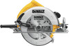
Dewalt DWE575 Instruction Manual - Page 12
Kerf Indicator Fig. 10, Cut Length Indicator Fig. 11, OPERATION, Proper Hand Position Fig. 12,
 |
View all Dewalt DWE575 manuals
Add to My Manuals
Save this manual to your list of manuals |
Page 12 highlights
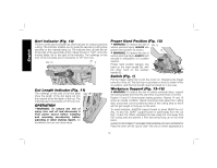
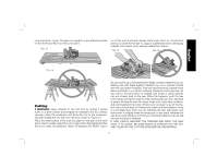
English Kerf Indicator (Fig. 10) The front of the saw foot plate has a kerf indicator for vertical and bevel cutting. This indicator enables you to guide the saw along cutting lines penciled on the material being cut. The indicator lines up with the left (inner) side of the saw blade which makes the slot or "kerf" cut by the moving blade, fall to the right of the indicator. The markings on the front of the foot plate are in increments of 1/8" (3.2 mm). FIG. 10 45˚ 0˚ Cut Length Indicator (Fig. 11) The markings on the side of the foot plate show the length of the slot being cut into FIG. 11 the material at the full depth of the cut. The markings are in increments of 1/8" (3.2 mm). OPERATION WARNING: To reduce the risk of injury, turn unit off and disconnect it from power source before installing and removing accessories, before adjusting or when making repairs. An accidental start-up can cause injury. Proper Hand Position (Fig. 12) WARNING: To reduce the risk of FIG. 12 serious personal injury, ALWAYS use proper hand position as shown. B WARNING: To reduce the risk of serious personal injury, ALWAYS hold securely in anticipation of a sudden reaction. Proper hand position requires one hand on the main handle (B), with E the other hand on the auxiliary handle (E). Switch (Fig. 1) Pull the trigger switch (A) to turn the motor on. Releasing the trigger turns the motor off. This tool has no provision to lock the switch in the on position, and the tool should never be locked on in any way. Workpiece Support (Fig. 13-16) WARNING: To reduce the risk of serious personal injury, support the work properly and hold the saw firmly to prevent loss of control. Figures 13 and 15 show proper sawing position. Figures 14 and 16 show an unsafe condition. Hands should be kept away from cutting area, and power cord is positioned clear of the cutting area so that it will not get caught or hung up on the work. To avoid kickback, ALWAYS support board or panel NEAR the cut, (Fig. 13 and 15). DON'T support board or panel away from the cut (Fig. 14 and 16). When operating the saw, keep the cord away from the cutting area and prevent it from becoming hung up on the work piece. ALWAYS DISCONNECT SAW BEFORE MAKING ANY ADJUSTMENTS! Place the work with its "good" side-the one on which appearance is 10
-
 1
1 -
2
-
3
-
4
-
5
-
6
-
 7
7 -
 8
8 -
 9
9 -
 10
10 -
 11
11 -
 12
12 -
 13
13 -
 14
14 -
 15
15 -
 16
16 -
 17
17 -
18
-
19
-
20
-
21
-
22
-
23
-
24
-
25
-
26
-
27
-
28
-
29
-
30
-
31
-
32
-
33
-
34
-
35
-
36
-
37
-
38
-
39
-
40
-
41
-
42
-
43
-
44
-
45
-
46
-
47
-
48
-
49
-
50
-
51
-
52
-
53
-
54
-
55
-
56
-
57
-
58
-
59
-
60
 |
 |
