Dewalt DWS535T Instruction Manual - Page 11
Important, To Remove Knockout, To Install The, Blade, Fig. 1, 10, 11
 |
View all Dewalt DWS535T manuals
Add to My Manuals
Save this manual to your list of manuals |
Page 11 highlights
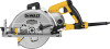
English arbor center is exposed. Only blades with a diamond-shaped arbor center can be used on this saw. NOTICE: Never install a blade without removing the knockout. Lack of blade engagement will cause the blade to come into contact with other parts of the saw causing tool damage. to remove knockout WARNING: Always use eye protection. All users and bystanders must wear eye protection that conforms to ANSI Z87.1. WARNING: Make sure that bevel adjusting locking lever is tight and secure after using it to remove knockout. If blade adjustment shifts while cutting it may cause binding and kickback. fig. 9 freely and does not touch the blade, foot plate or any other part, in all angles and depths of cut. 4. Place blade (T) on saw spindle (U) against the inner clamp washer (V), making sure that the blade will rotate in the proper direction (the direction of the rotation arrow on the saw blade and the teeth must point in the same direction as the direction of rotation arrow on the lower blade guard). IMPORTANT: Always ensure the diamond-shaped arbor center of the blade aligns with the raised diamond-shaped arbor center on the outer clamp washer. fig. 10 J J c Q Q Place the round center hole of the blade into the notch (Q) on the H top of the bevel adjustment lever (H). Grasping the saw and blade Q firmly, pull until the knockout pops out. The diamond-shaped arbor center is now exposed. TO INSTALL THE BLADE (Fig. 1, 10, 11) 1. Loosen and remove the blade clamping screw (R) with the wrench provided, by turning it clockwise as indicated by the Q arrow on the outer clamp washer (S). 2. Remove outer clamp washer (S). 3. Using the lower blade guard retracting lever (C), retract the lower blade guard (E). IMPORTANT: When retracting the lower blade guard to install the blade, check the condition and operation of the lower blade guard to assure that it is working properly. Make sure it moves 9 U V e T S R
-
 1
1 -
2
-
3
-
4
-
5
-
 6
6 -
 7
7 -
 8
8 -
 9
9 -
 10
10 -
 11
11 -
 12
12 -
 13
13 -
 14
14 -
 15
15 -
 16
16 -
17
-
18
-
19
-
20
-
21
-
22
-
23
-
24
-
25
-
26
-
27
-
28
-
29
-
30
-
31
-
32
-
33
-
34
-
35
-
36
-
37
-
38
-
39
-
40
-
41
-
42
-
43
-
44
-
45
-
46
-
47
-
48
-
49
-
50
-
51
-
52
-
53
-
54
-
55
-
56
-
57
-
58
-
59
-
60
-
61
-
62
-
63
-
64
 |
 |
