Dewalt DWX723 Instruction Manual - Page 4
Preparation Fig. 2, ASSEMBLY, DW7232 Work Piece, Support and Length, Stops Fig. 3-4, Adjustable - miter saw stand used
 |
View all Dewalt DWX723 manuals
Add to My Manuals
Save this manual to your list of manuals |
Page 4 highlights
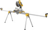
English • Follow the mounting instructions carefully. Fasten the miter saw to the saw mounting brackets securely as instructed. • DO NOT modify or use stand for operations for which it is unintended. • DO NOT use the stand on uneven surfaces. The stand is designed to be used on a flat, stable surface. • DO NOT use on a slippery surface. The stand load capacity is greatly reduced when used on slippery surfaces. Preparation (Fig. 2) 1. Place the miter saw stand on the ground FIG. 2 J with the folded legs facing up. K 2. Depress the leg lock lever (J) or release button (K) and pull leg up until the locking pin clicks into the place. Repeat on each leg. 3. Lift the stand by the center beam and place it in an upright position. The stand should be stable and should not rock. NOTE: Ensure all locking pins are engaged and the legs are locked in place. ASSEMBLY DW7232 Work Piece FIG. 3 Support and Length M Stops (Fig. 3-4) D a. The work support/stop (D) has L a clamp (L) to capture the beam and keep it from being knocked off the beam by your material. The knob (M) may be locked by turning clockwise and the work support/stop is free to be repositioned when the knob is turned counterclockwise. Do not overtighten, firm pressure on the knob will hold the stop in place. b. Adjust the height of the work support/stop (D) by loosening the knobs on both sides (N) and raise or lower the top surface to align with a straight edge or level to the saw table. Tighten the knobs. NOTE: If the work support height adjustment slips down when under a load, the weight limit of the work support has been exceeded. This weight limit is limited by the tightness of the height adjustment knobs. Do not tighten more than finger tight. FIG. 4 D N OE D c. The work support/stop (D) can also be installed in the end cap (E) at the end of the extension arms. d. The length stop (O) may be rotated up to serve as a length stop or hold the end of long work pieces. Adjustable Length FIG. 5 Extension Arm (Fig. 5) To lengthen the support surface, turn the extension arm lock lever counterclockwise to release the extendable extension arm. 2
-
 1
1 -
 2
2 -
 3
3 -
 4
4 -
 5
5 -
 6
6 -
 7
7 -
 8
8 -
 9
9 -
 10
10 -
11
-
12
-
13
-
14
-
15
-
16
-
17
-
18
-
19
-
20
-
21
-
22
-
23
-
24
-
25
-
26
-
27
-
28
-
29
-
30
-
31
-
32
 |
 |
