Dynex DX-TVM112 Quick Setup Guide (English) - Page 1
Dynex DX-TVM112 Manual
 |
View all Dynex DX-TVM112 manuals
Add to My Manuals
Save this manual to your list of manuals |
Page 1 highlights
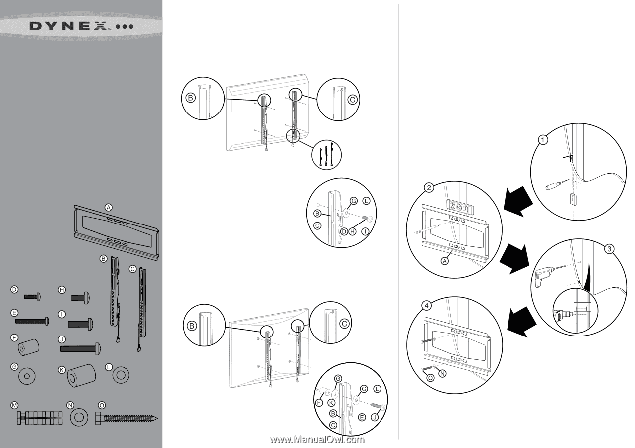
Low-Profile TV Mount QUICK SETUP GUIDE DX-TVM112 Thank you for choosing the Dynex DX-TVM112. The DX-TVM112 TV mount is designed to support a TV weighing up to 50 lbs. (22.7 kg). Package contents Tools you will need: A Wall plate (1) • Power drill B Left TV bracket (1) • 3/16 in. wood drill bit C Right TV bracket (1) • ½ in. masonry drill bit M4 bag • Phillips screwdriver D M4 x 12 mm screws (4) • Level E M4 x 30 mm screws (4) • Socket wrench with ½ in. socket or F M4 spacers (4) adjustable wrench G M4 washers (8) • Pencil M6 bag • Stud finder H M6 × 12 mm screws (4) • Awl I M6 × 20 mm screws (4) J M6 × 35 mm screws (4) K M6 spacers (4) L M6 washers (4) Lag bolt bag M Wall anchors (3) N 5/16 in. (7.9 mm) washers (3) O 5/16 in. × 2 ½ in. lag bolts (3) M4 Bag M6 Bag M4 × 12 mm M4 × 30 mm M6 × 12 mm M6 × 20 mm M4 M6 × 35 mm 1 Attach the TV brackets Option 1: Attaching to a TV with a flat back surface Attach the left and right TV brackets (B and C) to the back of the TV using: The M4 washers (G) and the M4 screws (D). Or The M6 washers (L) and the M6 screws (H or I). 2 Install the wall plate Option 1: Installing to a wood stud wall 1 Locate the stud. Verify the center of the stud with an awl or thin nail or use an edge to edge stud finder. 2 Level the wall plate (A) and mark the hole locations. 3 Drill the pilot holes as illustrated. 4 Align the wall plate (A) with the pilot holes, then place the washers (N) over the holes. Insert the lag bolts (O) through the washers, then tighten the lag bolts only until the washers are pulled firmly against the wall plate. DO NOT over-tighten the lag bolts (O). CAUTION: Avoid potential injuries or property damage! Any material covering the wall must not exceed 5/8 in. (16 mm). NOTE: Adjust to shorten or hide the cords NOTE: Determine if there is sufficient space between the back of the TV and the wall to connect all your cables before proceeding. or You may need to use the optional spacers to allow more clearance between the back of the TV and the wall. or or Option 2: Attaching to a TV with a rounded back surface Attach the left and right TV brackets (B and C) to the back of the TV using: The M4 spacers (F), M4 washers (G), and the M4 screws (E). Or The M6 spacers (K), M6 washers (L), and the M6 screws (J). 5/8 in. (
-
 1
1 -
 2
2
 |
 |