EVGA 121-BL-E756-TR User Manual - Page 21
pin ATX Power
 |
View all EVGA 121-BL-E756-TR manuals
Add to My Manuals
Save this manual to your list of manuals |
Page 21 highlights
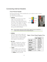
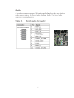
‰ USB 2.0 ‰ Expansion slots ‰ CMOS Clear Button 24-pin ATX Power (PW1) PW1 is the main power supply connector located along the edge of the board next to the DIMM slots. Make sure that the power supply cable and pins are properly aligned with the connector on the motherboard. Firmly plug the power supply cable into the connector and make sure it is secure. PW1 connector Plug power cable from system power supply to PW1 Figure 3. PW1 Motherboard Connector Table 1. PW1 Pin Assignments Connector 1 12 13 24 Pin Signal Pin Signal 1 +3.3V 13 +3.3V 2 +3.3V 14 -12V 3 GND 15 GND 4 +5V 16 PS_ON 5 GND 17 GND 6 +5V 18 GND 7 GND 19 GND 8 PWROK 20 RSVD 9 +5V_AUX 21 +5V 10 +12V 22 +5V 11 +12V 23 +5V 12 +3.3V 24 GND 22
-
 1
1 -
2
-
3
-
4
-
5
-
6
-
7
-
8
-
9
-
10
-
11
-
12
-
13
-
14
-
15
-
 16
16 -
 17
17 -
 18
18 -
 19
19 -
 20
20 -
 21
21 -
 22
22 -
 23
23 -
 24
24 -
 25
25 -
 26
26 -
27
-
28
-
29
-
30
-
31
-
32
-
33
-
34
-
35
-
36
-
37
-
38
-
39
-
40
-
41
-
42
-
43
-
44
-
45
-
46
-
47
-
48
-
49
-
50
-
51
-
52
-
53
-
54
-
55
-
56
-
57
-
58
-
59
-
60
-
61
-
62
-
63
-
64
-
65
-
66
-
67
-
68
-
69
-
70
-
71
-
72
-
73
-
74
 |
 |

22
USB 2.0
Expansion slots
CMOS Clear Button
24-pin ATX Power
(PW1)
PW1
is the main power supply connector located along the edge of the board
next to the DIMM slots. Make sure that the power supply cable and pins are
properly aligned with the connector on the motherboard. Firmly plug the power
supply cable into the connector and make sure it is secure.
Figure 3.
PW1 Motherboard Connector
Table 1.
PW1 Pin Assignments
Connector
Pin
Signal
Pin
Signal
1
+3.3V
13
+3.3V
2
+3.3V
14
-12V
3
GND
15
GND
4
+5V
16
PS_ON
5
GND
17
GND
6
+5V
18
GND
7
GND
19
GND
8
PWROK
20
RSVD
9
+5V_AUX
21
+5V
10
+12V
22
+5V
11
+12V
23
+5V
12
+3.3V
24
GND
PW1
connector
Plug power cable from system
power supply to PW1
1
12
13
24