EVGA 121-BL-E756-TR Visual Guide - Page 2
wello, 1OOOO
 |
View all EVGA 121-BL-E756-TR manuals
Add to My Manuals
Save this manual to your list of manuals |
Page 2 highlights
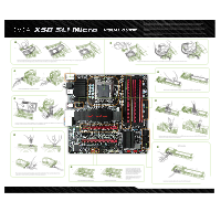
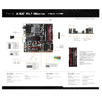
v i•NAX58 Micro VISUAL GUIDE Ground 12V Sense Fan Header - 8 Pin 12v Power Connector Pin Front Audio Connector 1 2 1 l• • 2 3 3• • 4 4 5 5• • 6 6 7 7 • 8 8 9 • • 10 9 10 Signal PORT1_L AUD_GND PORT1_R PRECENCE J PORT2_R SENSE1_RETURN SENSE_SEND Empty PORT2_L SENSE2_RETURN Connector SPDIF 2 4F • • • •0 1 3 5 Pin Definition 1 Power 2 No Pin 3 SPDIF 4 SPDIFI 5 GROUND 6 GROUND G ound 12V Sense G ound 12V Sense CPU Fan Header Control Sense 12V Ground 1, is 1n e. -dIeNm 4 n1$ am • WT':IL- •,tL 5 men•i. it /1/. •051 1. 111- lid ea , e-, 31- 10 1 • awn tigIggai"'2, P" Itf ••• +ice J• w. IMMO. 41.11 < " === r ellgt=== (r) (I) '03 I 111I~ ow. mu. mos '33 I • 4', • SOB 4144 aiiiii 4 4 55 6 Jel Er, lai ; Ad. , ,r al 55 kat' s # trOtr,. ' 7 .:. 4 • -. •jiair$33.iiviiviyula i REV.O. .^ •a• H4fifirik_. 6i t tl 1.10 415 Vidffd l651 . 01 wrip. pqm-, V 61 66 110/1 s°Q15,0 CM.° C7',3 g0 4••rmigg, S r11- 10PCI E:X16_1 nvioiA, .74 '. 11 7 . r.•ere MICA LI FA ial • da l 5 r" iPi Eligigfdt a .:*:--1.-.IN!!•t:1&1 ! 0 1-°I.V0 P.iff tr 0'77; ;.1.33 ,T. Roln "S.. :-:--.011141 CE 1 • . I s. , # I ;7.22 er.,111r00 MIME_ _1,2) 401 MTh 2.1=1 -• - 4 6.1 11511 t 0 ,4.1.7,,1 ' •-•/,.. V laiistHva Agrilni414,4111 , I 4 24 Pin ATX Power 3; ; RX- TX- FIX+ TX+ GND I GND I I GND SATA Ports Post LED CMOS Power Button Reset Button Fan Header Connector Pin IEEE 1394a Connector 1 r y Ter y, 2 2 4 6 8 10 3 4 5 l1 6 AL 47 135 79 8 9 10 Signal TPA+ TPAGND GND TPB+ TPB+12V +12V Empty GND PWRLED PWRSW Blank wello 1OOOO 9 + HD_LED RESET No Connect Connector USB 2.0 Header Connector 1 3579 I V V V • 9 I Ak Ak 2 4 6 8 10 Signal 5V_DUAL D- 4 D+ 6 GND 8 QM= 10 Signal 5V_DUAL DD+ GND No Connect Please see the manual for more details. "AG. 5 IF WIT 2 1. PS/2 Keyboard Port 2. USB 2.0 Ports 3. Coaxial SPDIF Output 2 4. Optical SPDIF Output 5. LAN Ports (10/100/1000) 6. Audio Ports tst Cw• 0°1 4 One DIMM: If using 1 DIMM (Single Channel), install into: DIMM slot 1. Two or Four DIMMs: If using 2 DIMMs (Dual Channel), install into: DIMM slots 1 and 3. If using 4 DIMMs (Dual Channel), install into: DIMM slots 2, 1, 4, and 3. Three DIMMs: If using 3 DIMMs (Triple Channel), install into: DIMM slots 1, 3, and 5. Six DIMMs: If using more than 4 DIMMs, use: DIMM slots 2, 1, 4, and 3 then proceed to occupy the following DIMM slots in this order: 5 and 6. ATTENTION: EVGA recommends applying 1.65V or less when setting the DIMM Voltage. This will support long term stability. vV`7A® Premium Services Advanced RMA: Protect yourself and accelerate the RMA process. www.evga.com/EAR 1+1 Warranty: Register the purchased product within 30 days to receive 2 year warranty. www.evga.com/warranty MODS RIGS: Show off your rig, post your specs, submit your score, and win big. www.modsrigs.com V3A. ZIP, Software E-LEET: Easily push the boundaries of your hardware with this exclusive tuning utility. www.evga.com/eleet Support 24/7 Support 888 • 881. EVGA *27/7 North America only www.evga.com/24-7 Thank you for purchasing an EVGA product. Please remember to register your product at: www.evga.com/register For the latest drivers and updates for your product please visit: www.evga.com/support/drivers To visit and search our knowledge base and product FAQ please visit: www.evga.com/FAQ To visit the EVGA community message boards please visit: forums.evga.com For more information about these services as well as our terms and conditions please visit www.evga.com EVGA Corp. 2900 Saturn Street, Suite B Brea, CA 92821
-
 1
1 -
 2
2
 |
 |
