EVGA 122-CK-NF68-A1 User Manual - Page 66
Installing the CPU Fan, Installing Memory DIMMs
 |
UPC - 843368000820
View all EVGA 122-CK-NF68-A1 manuals
Add to My Manuals
Save this manual to your list of manuals |
Page 66 highlights
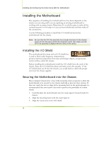
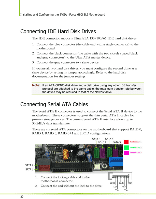
Hardware Installation Installing the CPU Fan There are many different fan types that can be used with this motherboard. Follow the instruction that came with you fan assembly. Be sure that the fan orientation is correct for your chassis type and your fan assembly. Installing Memory DIMMs Your new motherboard has four 1.8V 240-pin slots for DDR2 memory. These slots support 256 Mb, 512 Mb and 1 Gb DDR2 technologies for x8 and x16 devices. They also support dual channel DDR2 memory technology up to 10.7GB/s. There must be at least one memory bank populated to ensure normal operation. Use the following the recommendations for installing memory. ‰ One DIMM: Install into slot 0. You can install the DIMM into any slot, however, slot 0 is preferred. ‰ Two DIMMs: Install into either slots 0 and 1 or 2 and 3. The idea is to not have the DIMMs in adjacent slots. ‰ Four DIMMS: Install into slots 0, 1, 2, and 3. CPU side DIMM Slot 0 DIMM Slot 2 DIMM Slot 1 DIMM Slot 3 Card-edge side Use the following procedure to install memory DIMMs into the slots on the motherboard. Note that there is only one gap near the center of the DIMM slot. This slot matches the slot on the memory DIMM to ensure the component is installed properly. 43.Unlock a DIMM slot by pressing the module clips outward. 44. Align the memory module to the DIMM slot, and insert the module vertically into the DIMM slot. The plastic clips at both sides of the DIMM slot automatically lock the DIMM into the connector. 15
-
 1
1 -
2
-
3
-
4
-
5
-
6
-
7
-
8
-
9
-
10
-
11
-
12
-
13
-
14
-
15
-
16
-
17
-
18
-
19
-
20
-
21
-
22
-
23
-
24
-
25
-
26
-
27
-
28
-
29
-
30
-
31
-
32
-
33
-
34
-
35
-
36
-
37
-
38
-
39
-
40
-
41
-
42
-
43
-
44
-
45
-
46
-
47
-
48
-
49
-
50
-
51
-
52
-
53
-
54
-
55
-
56
-
57
-
58
-
59
-
60
-
 61
61 -
 62
62 -
 63
63 -
 64
64 -
 65
65 -
 66
66 -
 67
67 -
 68
68 -
 69
69 -
 70
70 -
 71
71 -
72
-
73
-
74
-
75
-
76
-
77
-
78
-
79
-
80
-
81
-
82
-
83
-
84
-
85
-
86
-
87
-
88
-
89
-
90
-
91
-
92
-
93
-
94
-
95
-
96
-
97
-
98
-
99
-
100
-
101
-
102
-
103
-
104
-
105
-
106
-
107
-
108
-
109
-
110
-
111
-
112
-
113
-
114
-
115
-
116
-
117
-
118
-
119
-
120
-
121
-
122
-
123
-
124
-
125
-
126
-
127
-
128
-
129
-
130
-
131
-
132
-
133
-
134
-
135
-
136
-
137
-
138
-
139
-
140
-
141
-
142
-
143
-
144
-
145
-
146
-
147
-
148
-
149
-
150
-
151
-
152
-
153
-
154
-
155
-
156
-
157
-
158
-
159
-
160
-
161
-
162
-
163
-
164
-
165
-
166
-
167
-
168
-
169
-
170
 |
 |
