Edimax ET-913 V2 series Quick Install Guide - Page 5
II. TP port RJ-45, III. The Fiber Port, IV. DIP Switch Setting: LLF/LFP Function, V. Link Loss
 |
View all Edimax ET-913 V2 series manuals
Add to My Manuals
Save this manual to your list of manuals |
Page 5 highlights
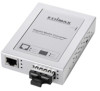
II. TP port (RJ-45) The device TP port support Auto-MDIX, Auto-Negotiation and Flow Control functions. The cable length up to 100 meters is for Cat5, Cat5e or Cat6 shielded/unshielded twisted-pair cable. III. The Fiber Port There're different types of fiber connectors, such as SC, LC and SFP for multi-mode or single-mode fiber cables. IV. DIP Switch Setting: (LLF/LFP Function) V. Link Loss Forwarding (LLF) / Link Fault Pass-through (LFP) Function When LLF/LFP function is enabled, no matter the device of TP port or fiber port is loose, linking status on TP or fiber port will inform their connected device. If the TP port is unplugged, the converter stops transmitting over the fiber port, causing the remote fiber node link to fail. The LED will show link failure on both the TP and fiber ports. If the fiber link fails, the converter causes the remote TP node link to fail. The LED also shows the link failure on both the TP and fiber ports. The figures below show normal status when the link succeeds and the error status on TP cable (A / D) or fiber cable (B/C) fails to 5
-
 1
1 -
 2
2 -
 3
3 -
 4
4 -
 5
5 -
 6
6 -
 7
7 -
 8
8 -
 9
9
 |
 |
