Electrolux E30GF74HPS Installation Instructions
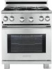
Electrolux E30GF74HPS - Icon - 30" Professional Series Gas Range Manual
 |
UPC - 057112101040
View all Electrolux E30GF74HPS manuals
Add to My Manuals
Save this manual to your list of manuals |
Electrolux E30GF74HPS manual content summary:
- Electrolux E30GF74HPS | Installation Instructions - Page 1
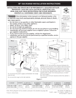
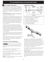
30" GAS RANGE INSTALLATION INSTRUCTIONS INSTALLATION AND SERVICE MUST BE PERFORMED BY A QUALIFIED INSTALLER. IMPORTANT: SAVE FOR LOCAL ELECTRICAL INSPECTOR'S USE. READ AND SAVE THESE INSTRUCTIONS FOR FUTURE REFERENCE. OBSERVE ALL GOVERNING CODES AND ORDINANCES. If the information in this manual is - Electrolux E30GF74HPS | Installation Instructions - Page 2
the oven. Wipe up excess spillage. Follow the cleaning instructions in the Use & Care Guide. • Unlike the standard gas range, THIS COOKTOP IS NOT REMOVABLE. Do not attempt to remove the cooktop. Special Instructions for appliances installed in the State of Massachusetts: This appliance can only be - Electrolux E30GF74HPS | Installation Instructions - Page 3
1000 ft. Important Note to the Consumer Keep these instructions with your owner's guide for future reference. Optional Items Available: • A Stainless Steel Kick plate • A Black Knob kit Those kits can be ordered for purchase through an Electrolux Service Center at 1-877-4ELECTROLUX (1-877-435 - Electrolux E30GF74HPS | Installation Instructions - Page 4
30" GAS RANGE INSTALLATION INSTRUCTIONS 3. Gas Supply Installation When shipped from the factory, this unit is designed to operate on 4"(10,16 cm) water column (1.0 kPa) Natural gas manifold pressure. A convertible pressure regulator is connected to the range manifold and MUST be connected in - Electrolux E30GF74HPS | Installation Instructions - Page 5
replacing the unit into the cut-out opening. Close the door and switch on the electrical power and gas to the range. Follow instructions for the type of installation you have Figure 6 If range will be installed with a cabinet on both sides, draw a center line on the floor between the cabinets (see - Electrolux E30GF74HPS | Installation Instructions - Page 6
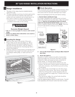
30" GAS RANGE INSTALLATION INSTRUCTIONS 7. Range Installation 1. The back of the range may be installed directly against the wall. 2. Turn on Electrical Power and Open Main Shutoff Gas Valve 3. Check the Igniters Operation of electric igniters should be checked after range and supply line - Electrolux E30GF74HPS | Installation Instructions - Page 7
30" GAS RANGE INSTALLATION INSTRUCTIONS 4. Adjust the "LOW" Setting of Regular Burner (see figure 8) on the Surface Burner Valves (Figure 9): a. Push in and turn control to LITE until burner ignites. b. Quickly turn knob to LOWEST POSITION. c. If burner goes out, reset control to OFF. d. Remove the - Electrolux E30GF74HPS | Installation Instructions - Page 8
30" GAS RANGE INSTALLATION INSTRUCTIONS 6. Operation of Oven Burners and Oven Adjustments 6.1 Electric Ignition Burners Operation of electric igniters should be checked after range and supply line connectors have been carefully checked for leaks, and range has been connected to electric power. The - Electrolux E30GF74HPS | Installation Instructions - Page 9
30" GAS RANGE INSTALLATION INSTRUCTIONS Important Safety Warning To reduce the risk of tipping of the range, the range must be secured to the floor by the properly installed anti-tip bracket and screws packed with the range. These parts are located in a plastic bag in the oven. 30" Range has one - Electrolux E30GF74HPS | Installation Instructions - Page 10
NOTES: 30" GAS RANGE INSTALLATION INSTRUCTIONS 10 - Electrolux E30GF74HPS | Installation Instructions - Page 11
SI PERCIBE UN OLOR A GAS: • No trate de de MSG, número No pellizque el cordón eléctrico entre la estufa y la 90.8 cm) Min. 45 1/2" 36" (91.4 cm) Standard 30 1/16" 42 5/8" (108.3 cm) Max. ( 75.9 cm del cableado de este modelo está incluido en esta manual (vea la pagina 28) P/N 318201775 (0808) - Electrolux E30GF74HPS | Installation Instructions - Page 12
ambiental sin provocar encogimiento, deformación o decoloración. No instale la estufa sobre una alfombra al menos que coloque una manual de tipo "T" debe de instalarse en la línea de alimentación de gas hacia este electrodoméstico. No utilice película de aluminium a la base del horno u otra parte - Electrolux E30GF74HPS | Installation Instructions - Page 13
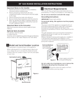
GAS Notas importantes para el Instalador 1. Lea todas las instrucciones contenidas en este manual juegos se pueden ordenar para comprar mediante Service Center 1-877-4ELECTROLUX (1-877-435- de Serie La placa de serie se encuentra en la parte trasera de la estufa Cuando haga pedidos de repuestos o - Electrolux E30GF74HPS | Installation Instructions - Page 14
se pellizque entre la pared y la estufa. Para verlo, saque el cajón. Las conexiones sugeridas en 30" modelo Valvula de FLUJO DEL GAS Regulador cierre Unión manual Unión de presión Abierto (On) Boquilla Apagado (Off) Conector flexible Boquilla Tapa de entrada Todas las conexiones - Electrolux E30GF74HPS | Installation Instructions - Page 15
eléctrica a la estufa a la fuente de poder principal, y cierre la válvula manual de gas. Asegúrese de que la estufa esté fría. Abra la puerta del horno. Levante de la abertura del armario en el piso (ver la figura 6). Si la parte trasera de la estufa no estará a ras con la pared (la ubicación del - Electrolux E30GF74HPS | Installation Instructions - Page 16
para conformar a los requisitos de A.G.A: - Para la estufa de 30" , un espacio mínimo de 7" (17.8 cm) debe de u otra parte de su cuerpo. 7.2 Comprobación del Funcionamiento Consulte el Manual del Usuario sido purgado de la tubería de suministro de gas. Controle visualmente que el quemador se hay - Electrolux E30GF74HPS | Installation Instructions - Page 17
INSTRUCCIONES DE INSTALACION PARA LA ESTUFA DE GAS 4. Ajuste bajo ("LO") para la válvula de los quemadores de superficie estandar (Figuras 8 y 9) a. Presione y gire el control hasta la posición LITE para prender los quemadores. b. - Electrolux E30GF74HPS | Installation Instructions - Page 18
una temperatura suficiente para encender el gas, la válvula del horno controlada desaparecerá por 20 a 30 segundos después de que los tornillos de ajuste del horno en la parte posteior del fondo del horno. jale hacia arriba de control de averías en su Manual del Usuario. Esto le podrá ahorrar - Electrolux E30GF74HPS | Installation Instructions - Page 19
DE INSTALACION PARA LA ESTUFA DE GAS Importante Advertencia de Seguridad Para reducir el ). Instrucciones de Instalación del Soporte Antivuelco 1. Estufa de 30": El soporte antivuelco debe de ser instalado en el lado derecho o izquierdo en la parte trasera de la unidad. 2. El soporte-base debe de - Electrolux E30GF74HPS | Installation Instructions - Page 20
WIRINGINDSTIARGUCRCAIOMN-ESDDIAEGINRSATAMLACDIOENLPAARINASLTAAELSATCUIFÓANDEAGLÁASMBRICA 20
-
 1
1 -
 2
2 -
 3
3 -
 4
4 -
 5
5 -
 6
6 -
 7
7 -
8
-
9
-
10
-
11
-
12
-
13
-
14
-
15
-
16
-
17
-
18
-
19
-
20
 |
 |
30" GAS RANGE INSTALLATION INSTRUCTIONS
If the information in this manual is not followed exactly, a fire
or explosion may result causing property damage, personal injury or death.
FOR YOUR SAFETY:
—
Do not store or use gasoline or other flammable vapors and liquids in
the vicinity of this or any other appliance.
—
WHAT TO DO IF YOU SMELL GAS:
•
Do not try to light any appliance.
•
Do not touch any electrical switch; do not use any phone in your building.
•
Immediately call your gas supplier from a neighbor's phone. Follow the
gas supplier's instructions.
•
If you cannot reach your gas supplier, call the fire department.
—
Installation and service must be performed by a qualified installer, service
agency or the gas supplier.
P/N 318201775 (0808) Rev. B
English - pages 1-10; Español - páginas 11-19
Wiring Diagram - page 20
Note: Wiring diagram for this model is enclosed in this booklet (see page 28).
Printed in United States
INSTALLATION AND SERVICE MUST BE PERFORMED BY A QUALIFIED INSTALLER.
IMPORTANT: SAVE FOR LOCAL ELECTRICAL INSPECTOR'S USE.
READ AND SAVE THESE INSTRUCTIONS FOR FUTURE REFERENCE.
OBSERVE ALL GOVERNING CODES AND ORDINANCES.
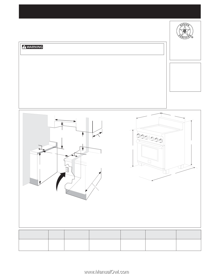
B.
WIDTH
29 7/8"
( 75.9 cm)
C.
DEPTH TO
FRONT OF RANGE
27 1/2"
(69.9 cm)
E.
DEPTH WITH
DOOR OPEN
45 1/2"
(115.6 cm)
F.
HEIGHT OF
COUNTERTOP
36" (91.4 cm) Standard
35 3/4" (90.8 cm) Min.
G.
MINIMUM
CUTOUT WIDTH
30 1/16"
(76.4 cm)
NOTE:
24" (61 cm) minimum clearance between the
cooktop and the bottom of the cabinet when the bottom
of wood or metal cabinet is protected by not less than
1/4" (0.64 cm) flame retardant millboard covered with
not less than No. 28 MSG sheet metal, 0.015" (0.4 mm)
stainless steel, 0.024" (0.6 mm) aluminum, or 0.020"
(0.5 mm) copper.
30" (76.2 cm) minimum clearance when the cabinet is
unprotected.
Do not pinch the power supply cord between the range
and the wall.
Do not seal the range to the side cabinets.
13" Max.
(33 cm Max.)
24" Min.
(61 cm Min.)
24 1/2" Max.
(62.2 cm Max.)
29 7/8" Min.
(75.9 cm Min.)
See
note
Recommended
Grounded
Wall Outlet
Location
WALL
WALL
If there is a wall:
5" Min.
(12.7 cm Min cm Min.)
Left side
18" Min.
(45.7 cm Min.)
F
G
If there is a wall:
5" Min.
(12.7 cm Min.)
Right side
A
B
C
D
E
Figure 1
Note:
For
appliances
installed in the
state of
Massachusetts
see page 2.
Refer to your
serial plate for
applicable agency
certification
A.
HEIGHT
41 5/8" (105.7 cm) Min.
42 5/8" (108.3 cm) Max.
D.
HEIGHT OF
COOKTOP
35 3/4" (90.8 cm) Min.
36 3/4" (93.3 cm) Max.