Electrolux E30GF74HPS Installation Instructions - Page 7
Adjust the LOW Setting of the Dual Burner see - gas range
 |
UPC - 057112101040
View all Electrolux E30GF74HPS manuals
Add to My Manuals
Save this manual to your list of manuals |
Page 7 highlights
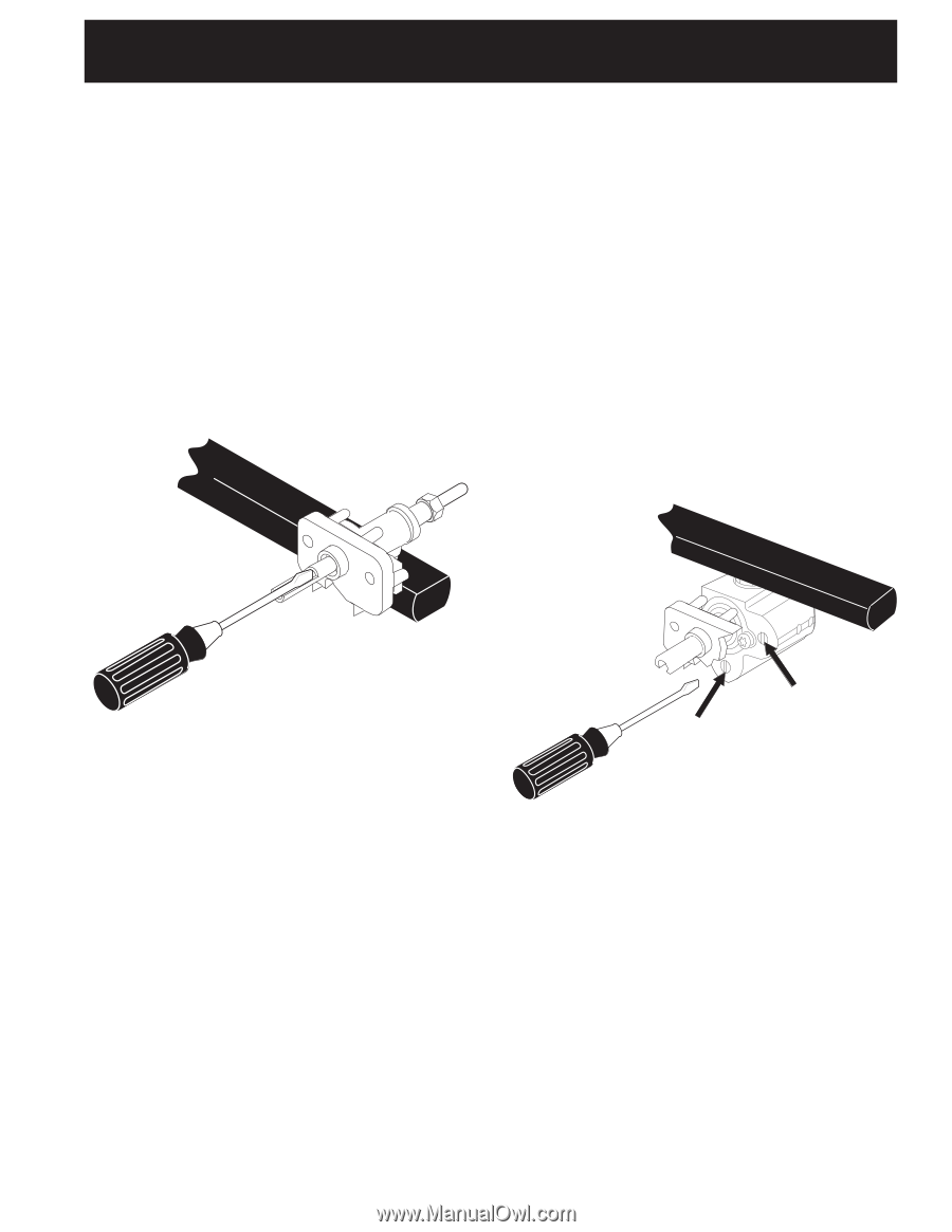
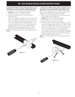
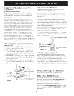
30" GAS RANGE INSTALLATION INSTRUCTIONS 4. Adjust the "LOW" Setting of Regular Burner (see figure 8) on the Surface Burner Valves (Figure 9): a. Push in and turn control to LITE until burner ignites. b. Quickly turn knob to LOWEST POSITION. c. If burner goes out, reset control to OFF. d. Remove the surface burner control knob and decorative ring. e. Insert a thin-bladed screwdriver into the hollow valve stem and engage the slotted screw inside. Flame size can be increased or decreased by turning the screw. Turn counterclockwise to increase flame size. Turn clockwise to decrease flame size. Adjust flame until you can quickly turn knob from LITE to LOWEST POSITION without extinguishing the flame. Flame should be as small as possible without going out. Note: Air mixture adjustment is not required on surface burners. 5. Adjust the "LOW" Setting of the Dual Burner (see Figure 8) on the Surface Burner Valve (Figure 10): Note: On the dual valve the low setting of each portion (rear portion of bridge burner and the center portion of bridge burner) should be adjusted individually. a. Push in and turn control to LITE until the rear portion of the bridge burner ignites only. b. Quickly turn knob to LOWEST POSITION. c. If burner goes out, reset control to OFF. d. Remove the surface burner control knob. e. The inner portion of the dual burner flame size can be increased or decreased by turning screw A (see Figure 10). Use screw B to adjust the flame size of the outer portion of the dual burner. Turn counterclockwise the screw to increase flame size. Turn clockwise the screw to decrease flame size. Adjust flame until you can quickly turn knob from LITE to LOWEST POSITION without extinguishing the flame. Flame should be as small as possible without going out. Note: Air mixture adjustment is not required on surface burners. Figure 9 B A Figure 10 7
-
 1
1 -
 2
2 -
 3
3 -
 4
4 -
 5
5 -
 6
6 -
 7
7 -
 8
8 -
 9
9 -
 10
10 -
 11
11 -
 12
12 -
13
-
14
-
15
-
16
-
17
-
18
-
19
-
20
 |
 |