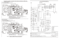
Electrolux E30MC75PPS Wiring Diagram English - Page 2
Electronic Oven Control EOC Fault Code Descriptions
 |
View all Electrolux E30MC75PPS manuals
Add to My Manuals
Save this manual to your list of manuals |
Page 2 highlights
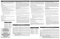
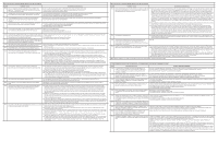
Electronic Oven Control (EOC) Fault Code Descriptions Code Condition / Cause Suggested Corrective Action F10 The oven control has sensed a potential runaway condition in the lower oven. The Appliance Control Board may have a shorted relay, RTD sensor may have gone bad. If oven is overheating, disconnect power. Check RTD sensor probe and replace if necessary. If oven continues to overheat when power is reapplied, replace Appliance Control Board. If problem persists replace the User Interface Board. F11 Shorted keypad: key has been detected as pressed for a long period If a key was pressed inadvertently for a long time the fault code should go away once the key is released. and is triggering a shorted key alarm, terminating all oven activity. If the fault code cannot be cleared the touch panel is most likely defective (replace touch panel). If changing the touch panel did not fix the problem replace the User Interface Board. F13 Incorrect EEPROM checksum: the control (User Interface Board or Appliance Control Board) internal memory maybe have become corrupted. Disconnect power, wait 30 seconds and reapply power. If fault returns upon power-up, replace the Appliance Control Board. If problem persists replace the User Interface Board. F14 Misconnected flat cable. The User Interface Board does not see the glass touch panel as being well connected (4 flat cables). Check the 4 flat cables connections between the User Interface Board (J4, J6, J8, J9) and the touch panel. Make sure the cables are fully inserted into the connectors. Check for bent pins and verify cable integrity. If all 4 cables appear to be good replace the User Interface Board. If the problem persists replace the touch panel. F15 Controller self check failed. The User Interface Board or the Appliance Replace the User Interface Board. Control Board has detected a problem with its internal circuit. If the problem persists replace the touch panel. If the problem persists replace the Appliance Control Board. F20 Communication problem between the User Interface Board and the Check the communication harness from connector P20 (pins 1,2,7,9,11) on the Appliance Control Board to connector J2 on the User Appliance Control Board: the User Interface Board is not able to initiate Interface Board. communication with the Appliance control board. If the problem persists replace the Appliance Control Board. If the problem persists replace the User Interface Board. F21 Communication problem between the User Interface Board and the Appliance Control Board: the User Interface Board is no longer able to detect communication from the Appliance control board. F30 Open RTD sensor probe/ wiring problem: the Appliance Control board Check wiring in lower oven probe circuit for possible open or short condition sees the lower oven temperature probe as being an open circuit. Check RTD resistance at room temperature (compare to probe resistance chart). If resistance does not match the chart, replace the F31 Shorted RTD sensor probe/ wiring problem: the Appliance Control board sees the lower oven temperature probe as being a short circuit. RTD sensor probe. Let the oven cool down and restart the function. If the problem persists, replace the Appliance Control Board. F43 The microwave «external» cooling fan speed (as read by the tachometer input of the Appliance Control Board) is abnormally slow Check if the microwave "external" cooling fan (the one outside of the microwave chassis) is turning. This fan is supposed to be active anytime the microwave is used and is expected to remain ON for a few minutes after the microwave has stopped. A fan not turning at all or a fan abnormally slow will trigger an F43 fault code Check the connection to the cooling fan speed sensor from P19 on the appliance control board to the sensor located on the fan. If the fan is not turning or turns very slowly check the 120VAC voltage on the fan. If 120VAC is present at the fan but the fan does not physically turn replace the fan. If 120VAC is not present check the wiring from the Appliance Control Board (is there 120VAC on P16? Is the fan correctly connected between P15 and Neutral?). If the cooling fan appears to turn normally but an F43 fault code is generated it means there is a problem with the reading of the fan speed sensor. Make sure the connection to the fan sensor is properly made and make sure it is connected to connector P19 on the Appliance Control Board. Make sure the wires in this harness go to the right connector pins. If the wiring is good replace the cooling fan. If the problem persists replace the Appliance Control Board. F44 The microwave «external» cooling fan speed (as read by the tachometer input of the Appliance Control Board) is abnormally high Visually inspect the microwave «external» cooling fan (the one outside of the microwave chassis). This fan is supposed to be active anytime the microwave is used and is expected to remain ON for a few minutes after the microwave has stopped. A fan turning abnormally fast will trigger an F44 fault code. Verify the mechanical construction of the fan. Verify there is nothing blocking the air flow of the fan (that would make the fan turn faster). Check the 120VAC voltage on the fan. A voltage higher than 120VAC + 10% could make it go too fast. If the cooling fan appears to turn normally but an F44 fault code is generated there could be a problem with the reading of the fan speed sensor. Make sure the connection to the fan sensor is properly made and make sure it is connected to connector P19 on the Appliance Control Board. Make sure the wires in this harness go to the right connector pins. If the wiring is good replace the cooling fan. If the problem persists replace the Appliance Control Board. F61 Loss of zero-cross synchronization signal at the ACB Verify the appliance control board (ACB) is connected to L1 on connector J1 pin 1 and to neutral on connector J1 pin 2. If the line and neutral connector is good and problem persist replace the ACB. F62 Loss of the zero-cross synchronization signal at the user interface board. Verify the zero-cross signal from ACB connector P20 pin 3 is properly connected to the user interface board on connector J1 pin 3. If the problem persist replace the user interface board. F80 Communication problem between the User Interface Board and the Microwave Control Board: the User Interface Board is not able to initiate communication with the Microwave Control Board. Verify if the microwave is powered (120VAC) by doing this simple test: Open the microwave door and check if the microwave light (inside the cavity) turns ON or not. If it does not turn ON it means the microwave and it's controller have no power and it explains why the Microwave Control Board is not able to communicate with the User Interface Board. In that event an investigation must be done to find out why it has not power: it could be a fuse opened (fuse external to the microwave chassis or fuse internal to the microwave chassis). A fuse could be opened due to an over-current or a microwave door switch problem (see door switch adjustment section). If the F80 error occurred while the oven was hot there is a possibility the fault code was caused be a microwave thermal cut-out that opened. Verify nothing is blocking the air flowing out of the microwave and verify cooling fans (internal and external) are working. Note that a thermal cut-out will close once the unit cools down. A continuity check across the thermal cut-out terminals can be done. Refer to the thermal cut-out section. If the microwave appears to be powered (fuses and thermal cut-outs ok) but there is still no communication between the User Interface Board and the Microwave Control Board verify the wire harness that connects the two boards, from J3 on the User Interface Board to connector «D» on the Microwave Control Board. If the harness is good there could be a problem with the User Interface board. Try replacing it. If the problem persists replace the Microwave Control Board. F81 Damper Error. The Microwave Control Board reports that it is not able Expected operation: when the micro-combi unit is plugged in, the damper motor operates (relay RY4) until the damper is opened and the to detect the proper position of the damper. damper switch closes. Then the damper motor stops operation. If the Microwave Control Board is not reading the position of the damper as opened, the F81 error will also be generated when using microwaves functions (non-convection). When a convection function is started the Microwave Control Board attempts to move the damper to the closed position by energizing the damper motor and reading the damper switch. If after 59 seconds it has not seen the closed position the microwave stops and the F81 fault code is generated. If the damper motor does not turn, verify it is getting 120VAC from the Microwave Control Board. If 120VAC is present but the motor still does not turn replace the motor. If 120VAC is not present check the wire harness and the Microwave Control Board. If the damper motor is good check the damper switch. When switch actuator is pushed by the damper motor cam, a meter should indicate a closed circuit. When power cord is plugged into the wall receptacle, the damper motor operates and damper cam will start to rotate. When the switch actuator is released, a meter should be indicating an open circuit. If improper operation is indicated, replace the damper switch. Electronic Oven Control (EOC) Fault Code Descriptions Code Condition / Cause Suggested Corrective Action F82 Microwave thermistor open error. The microwave control is not able to The fault code could have been generated because the convection element is not heating. In that case the microwave operation stops read correctly the temperature in the microwave cavity, or there is no after approximately 4 minutes and 15 seconds and generates the F82 fault code. Verify the operation of the microwave convection heat generated by the convection element. element. Start a convection function (ex: Conv Bake 350F for 10 minutes), wait a few minutes. Check if you see the temperature rising or not in the unit's display. You can also try to touch the left side wall in the microwave cavity (where the convection element is located) to see if the element is heating or not, but take care not to burn yourself. The convection element can also be tested using this procedure: Disconnect power supply cord, and remove outer case. Open the door and block it open. Discharge high voltage capacitor. Make sure the heating element is fully cooled and test as follows: Disconnect wire leads and measure the resistance with an ohmmeter. The resistance between the heating element terminals should be approximately 10.2ohm. Disconnect wire leads and measure the insulation resistance with 500V - 100Mohm insulation resistance meter. The insulation resistance between heating element terminal and cavity should be more than 0.5Mohm. Reconnect all leads removed from components. Reinstall the outer case (cabinet). Another possible root cause for the convection element not heating could be a door switch problem. If the 3rd door switch is not closed whole the door is closed the convection element will not heat. Refer to the microwave door switches section. If the convection element is good the problem could come from the microwave thermistor. The thermistor can be tested following this procedure: disconnect power supply cord, and remove outer case. Open the door and block it open. Discharge high voltage capacitor. Disconnect connector-E from the microwave controller. Measure the resistance of the thermistor with an ohmmeter by connecting the ohmmeter leads to connector «E» Pin 3 and 4. At room temperature (68°F(20°C) - 86°F(30°C) the resistance should be approx. 350k - 155K. If the meter does not indicate a resistance within this range replace the thermistor. Reconnect all leads removed from components during testing. Reinstall the outer case (cabinet). Reconnect power supply cord after the outer case is installed. Run oven and check all functions. F83 Fire detected in microwave oven By sensing sudden changes of the microwave thermistor value the Microwave Control Board can detect a fire in the microwave cavity. In that event it terminates all microwave activity and generate an F83 fault code. Clear the condition that possibly created a fire in the cavity and test the microwave again. F84 Communication problem between the User Interface Board and See F80. the Microwave Control Board: the User Interface Board lost communication with the Microwave Control Board (loss of microwave communication «heart beat»). F90 Motor Door Latch mechanism failure. The oven control has not been able to lock or unlock the lower oven door successfully. Turn off power for 30 seconds, then turn on power. Try again to make the door lock or unlock (ex: initiate a Lockout or a Clean cycle). Check if the Lock Motor is turning or not. If it is not then check if there is 120VAC at the motor when it is expected to turn to see if the failure originates from a bad motor (120VAC present but not turning) or a problem with the relay board (J1 pin 4 on Appliance Control Board is the output to the Lock Motor). The Lock Motor can also be tested by applying 120VAC directly to the motor (unplug it from the Appliance Control Board first). Replace the Lock Motor or Appliance Control Board if necessary. If the Lock Motor is turning but the oven control cannot find the locked or unlocked position (ex: motor turns continuously until F90 fault code is generated) the Lock Switch needs to be verified. Check wiring to the Appliance Control Board. Verify with ohmmeter if the switch makes contact properly. If the Lock Switch is defective replace the Motor Lock Assembly. If all above steps failed to correct the situation, replace the Appliance Control Board. Note: Generally speaking, F1X implies a control failure, F3X an oven probe problem, and F9x a latch motor problem. CODES D'ERREUR POUR LA FICHE TECHNIQUE DE LA CUISINIÈRE AVEC BOUTONS DE COMMANDE À L'AVANT Code Description de l'erreur F10 Le contrôle de four a détecté une dérive potentielle dans le four du bas. Il peut s'agir d'un relais court-circuité dans le tableau de commande de l'appareil ou d'un capteur de température dont la résistance est erronée. Action corrective suggérée Si le four surchauffe, débrancher l'alimentation. Vérifier la sonde de capteur de température à résistance et la remplacer le cas échéant. Si le four continue à surchauffer après la remise en marche, remplacer le tableau de commande de l'appareil. Si le problème persiste, remplacer le module d'interface utilisateur. F11 Pavé numérique court-circuité : détection d'une touche enfoncée Si une touche demeure enfoncée par inadvertance, le code d'erreur doit disparaître une fois la touche relâchée. pendant une longue période, déclenchant une alarme < touche court- Si le code d'erreur ne disparaît pas, l'écran tactile est le plus susceptible d'être défectueux (remplacer l'écran tactile). circuitée > et arrêtant toute activité du four. Si le remplacement de l'écran tactile ne règle pas le problème, remplacer le module d'interface utilisateur. F13 Erreur de somme de contrôle d'EEPROM : la mémoire intégrée (module Débrancher l'alimentation, attendre 30 secondes, puis redémarrer. Si la panne réapparaît à la mise sous tension, remplacer le tableau d'interface utilisateur ou tableau de commande de l'appareil) est de commande de l'appareil. possiblement corrompue. Si le problème persiste, remplacer le module d'interface utilisateur. F14 Câble plat mal branché. Le module d'interface utilisateur détecte un mauvais branchement de l'écran tactile (4 câbles plats). Vérifier les 4 branchements des câbles plats entre le module d'interface utilisateur (J4, J6, J8, J9) et l'écran tactile. S'assurer que les câbles plats sont bien insérés dans les connecteurs. Chercher d'éventuelles broches tordues et vérifier l'intégrité des câbles. Si les 4 câbles semblent en bon état, remplacer le module d'interface utilisateur. Si le problème persiste, remplacer l'écran tactile. F15 Échec d'autovalidation du contrôleur. Le module d'interface utilisateur Remplacer le module d'interface utilisateur. ou le tableau de commande de l'appareil a détecté un problème Si le problème persiste, remplacer l'écran tactile. interne. Si le problème persiste, remplacer le tableau de commande de l'appareil. F20 Problème de communication entre le module d'interface utilisateur et Vérifier le faisceau de communication de la fiche P20 (broches 1, 2, 7, 9 et 11) du tableau de commande de l'appareil à la prise J2 du le tableau de commande de l'appareil : le module d'interface utilisateur module d'interface utilisateur. est incapable d'établir la communication avec le tableau de commande Si le problème persiste, remplacer le tableau de commande de l'appareil. de l'appareil. Si le problème persiste, remplacer le module d'interface utilisateur. F21 Problème de communication entre le module d'interface utilisateur et le tableau de commande de l'appareil : le module d'interface utilisateur n'établit plus la communication avec le tableau de commande de l'appareil. F30 Sonde du capteur de température à résistance ou câblage ouvert : le Chercher un court-circuit ou un circuit ouvert dans l'installation électrique du circuit de sonde du four inférieur tableau de commande de l'appareil voit la sonde de température de Vérifier le capteur de température à résistance à la température ambiante (comparer au graphique de résistance de la sonde). Si la four inférieur comme un circuit ouvert. résistance n'égale pas le graphique, remplacer la sonde de capteur de température à résistance. F31 Sonde du capteur de température à résistance ou câblage court- Laisser refroidir le four et relancer la fonction. Si le problème persiste, remplacer le tableau de commande de l'appareil. circuité : le tableau de commande de l'appareil voit la sonde de température de four inférieur comme un court-circuit. F43 La vitesse du ventilateur « externe » du four à micro-ondes (lue par le Vérifier si le ventilateur « externe » (situé hors du châssis) du four à micro-ondes tourne. Ce ventilateur est censé être en marche chaque tachymètre du tableau de commande de l'appareil) est anormalement fois que le four à micro-ondes est utilisé et doit demeurer EN MARCHE pendant quelques minutes après l'arrêt du four à micro-ondes. Un lente. ventilateur qui ne tourne pas ou un ventilateur anormalement lent génère le code d'erreur F43 Vérifier la connexion au capteur de vitesse du ventilateur de P19 sur le tableau de commande d'appareil au capteur localisé sur le ventilateur. Si le ventilateur ne tourne pas ou tourne très lentement, vérifier la tension de 120 V CA du ventilateur. Si elle est présente, mais le venti- lateur ne tourne pas, remplacer le ventilateur. Si elle est absente, vérifier le câblage du tableau de commande de l'appareil (la tension de 120 V CA est-elle présente à la fiche P16? Le ventilateur est-il correctement branché entre la fiche P15 et le neutre?) Si le ventilateur semble tourner normalement, mais qu'un code d'erreur F43 est généré, cela indique une anomalie de lecture du capteur de vitesse du ventilateur. Valider la connexion du capteur de ventilateur et s'assurer qu'il est branché à la prise P19 du tableau de com- mande de l'appareil. S'assurer que les fils du faisceau sont raccordés aux bonnes broches du connecteur. Si le câblage est en bon état, remplacer le ventilateur. Si le problème persiste, remplacer le tableau de commande de l'appareil.
-
 1
1 -
 2
2 -
 3
3 -
 4
4
 |
 |
