Electrolux E30MC75PPS Installation Instructions English - Page 5
Important Note
 |
View all Electrolux E30MC75PPS manuals
Add to My Manuals
Save this manual to your list of manuals |
Page 5 highlights
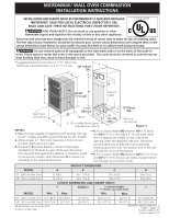
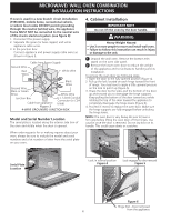
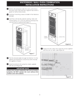
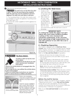
MICROWAVE/ WALL OVEN COMBINATION INSTALLATION INSTRUCTIONS 3 Remove all packaging inside the ovens and remove the lower oven racks and their supports (see owner's guide for further instructions). 4 Find the 2 mounting screws included in the literature package. 5 Insert the unit into the cabinet opening. Slide unit inward leaving 1½" (3.8 cm) clearance between the unit and front of cabinet (see Figure 7). Screws supplied Bottom Trim 1½" (3.8 cm) clearance between unit Figure 7 Figure 8 8 Install now the center trim using the screws supplied with the unit, on both sides (Figure 9). 6 Pull the armored cable through the hole for it in the cabinet and toward the junction box while moving the appliance inward. 7 Install the bottom trim using the screws supplied with the unit (Figure 8). IMPORTANT NOTE Bottom trim must be installed for the oven to function properly. DO NOT operate the oven without the bottom oven trim installed. Figure 9 5
-
 1
1 -
 2
2 -
 3
3 -
 4
4 -
 5
5 -
 6
6 -
 7
7 -
 8
8 -
 9
9 -
 10
10 -
 11
11 -
12
-
13
-
14
-
15
-
16
-
17
-
18
-
19
-
20
 |
 |
