Electrolux E36DF76TPS Wiring Diagram English - Page 1
Electrolux E36DF76TPS Manual
 |
View all Electrolux E36DF76TPS manuals
Add to My Manuals
Save this manual to your list of manuals |
Page 1 highlights
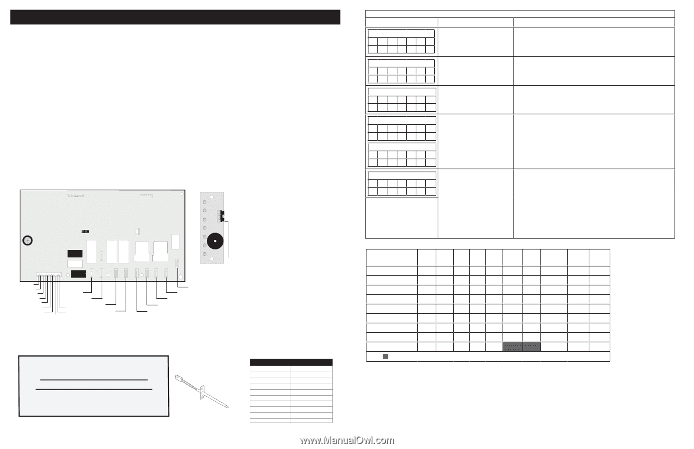
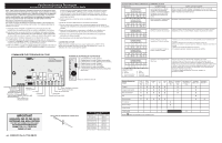
SERVICE DATA SHEET Dual Fuel Range with ES 570 Electronic Oven Control A NOTICE - This service data sheet is intended for use by persons having electrical and mechanical training and a level of knowledge of these subjects generally considered acceptable in the appliance repair trade. The manufacturer cannot be responsible, nor assume any liability for injury or damage of any kind arising from the use of this data sheet. SAFE SERVICING PRACTICES To avoid the possibility of personal injury and/or property damage, it is important that safe servicing practices be observed. The following are examples, but without limitation, of such practices, 1. Do not attempt a product repair if you have any doubts as to your ability to complete it in a safe and satisfactory manner. 2. Before servicing or moving an appliance, remove power cord from electric outlet, trip circuit breaker to OFF, or remove fuse and turn off gas supply. 3. Never interfere with the proper installation of any safety device. 4. USE ONLY REPLACEMENT PARTS CATALOGED FOR THIS APPLIANCE. SUBSTITUTIONS MAY DEFEAT COMPLIANCE WITH SAFETY STANDARDS SET FOR HOME APPLIANCES. 5. GROUNDING: The standard color coding for safety ground wires is GREEN OR GREEN WITH YELLOW STRIPES. Ground leads are not to be used as current carrying conductors. IT IS EXTREMELY IMPORTANT THAT THE SERVICE TECHNICIAN REESTABLISH ALL SAFETY GROUNDS PRIOR TO COMPLETION OF SERVICE. FAILURE TO DO SO WILL CREATE A POTENTIAL HAZARD. 6. Prior to returning the product to service, ensure that: • All electric connections are correct and secure. • All electrical leads are properly dressed and secured away from sharp edges, high-temperature components, and moving parts. • All non-insulated electrical terminals, connectors, heaters, etc. are adequately spaced away from all metal parts and panels. • All safety grounds (both internal and external) are correctly and securely reassembled. • All panels are properly and securely reassembled. Oven Calibration Set the electronic oven control for normal baking at 350°F. Obtain an average oven temperature after a minimum of 5 cycles. The oven calibration can not be modified. Electronic oven control relay board Electronic Display Board To display board 1P8 1 P9 D1 To potentiometer selector and temperature potentiometer D2 D3 D4 P6 P14 D5 K4 K3 P16 K1 K2 K5 MDL 1 K11 Conv. Broil Bake P4 P1 P3 P2 P5 Lamp switch Oven probe Oven probe Convection Element MDL switch L1 Door switch Lamp switch N Cooling fan- high 120V to MDL Cooling fan- low Broil Bake D6 Conv. DLB DLB K10 D7 bake & broil conv. P15 K6 K7 P10 P11 P12 P13 Convection fan L2 in (convection) L2 out (convection) L2 in L2 out (bake & broil) This display board serves for Freestanding Range D1- Bake Mode Indicator Light D2- Convection Bake Mode Indicator Light D3- Convection Roast Mode Indicator Light D4- Broil Mode Indicator Light D5- Clean Mode Indicator Light D6- Lock Mode Indicator Light D7- Racks Indicator Light Goes to P8 oven control. IMPORTANT DO NOT REMOVE THIS BAG OR DESTROY THE CONTENTS WIRING DIAGRAMS AND SERVICE INFORMATION ENCLOSED REPLACE CONTENTS IN BAG p/n 809008415 Rev A (1708) EN-FR Resistance Temperature Detector RTD SCALE Temperature °F (°C) Resistance (ohms) 32 ± 1.9 (0 ± 1.0) 1000 ± 4.0 75 ± 2.5 (24 ± 1.3) 1091 ± 5.3 250 ± 4.4 (121 ± 2.4) 1453 ± 8.9 350 ± 5.4 (177 ± 3.0) 1654 ± 10.8 450 ± 6.9 (232 ± 3.8) 1852 ± 13.5 550 ± 8.2 (288 ± 4.5) 2047 ± 15.8 650 ± 9.6 (343 ± 5.3) 2237 ± 18.5 900 ± 13.6 (482 ±7.5) 2697 ± 24.4 Probe circuit to case ground Open circuit/infinite resistance ELECTRONIC OVEN CONTROL (EOC) FAULT CODE DESCRIPTIONS Failure Code Likely Failure Condition/Cause Suggested Corrective Action Front Panel LED 1 2 3 4 5 67 X X Front Panel LED 1 2 3 4 5 67 X X Control has sensed a potential runaway oven condition. Control may have shorted relay, RTD sensor probe may have gone bad. Incorrect Micro ID, controller self check failed. Check RTD sensor probe and replace if necessary. If oven is overheating, disconnect power. If oven continues to overheat when power is reapplied, replace control board. Replace the control board. Front Panel LED 1234567 X X Incorrect EEPROM Checksum, control internal checksum may have been corrupted. Disconnect power, wait 30 seconds and reapply power. If fault returns upon power-up, replace control board. Front Panel LED 1234567 X X Front Panel LED 1234567 X X Open RTD sensor probe / wiring problem. - Check wiring in probe circuit for possible open condition. - Check RTD resistance at roon temperature (compare to probe resistance chart). If resistance does not match the chart, replace RTD sensor probe. - Let the oven cool down and restart the function. - If problem persist, replace control board. Shorted RTD sensor probe / wiring problem. Front Panel LED 1234567 XXX LED Legend: 1 - Bake 2 - Convection Bake 3 - Convection Roast 4 - Broil 5 - Clean 6 - Lock 7 - Remove racks Door motor mechanism failure. - Turn off power for 30 seconds, then turn on power. - Check wiring of lock motor, lock switch circuits. - Unplug the lock motor from the board and apply power (L1) directly to the lock motor. If the motor does not rotate, replace the lock motor assembly. - Check lock switch for proper operation (do they open and close, check with ohmmeter). The lock motor may be powered as in above step to open and close lock switch. If the lock switch is defective, replace motor lock assembly. - If all above steps fail to correct situation, replace the control board. Circuit Analysis Matrix Bake Convection Bake Convection Roast Broil Self-Clean Locking Unlocking Door Open Door Closed DLB1 L2 out P10 X X X X X DLB2 L2 out P12 X Bake P2 X Broil P3 X X X X X X X X X X X Conv P4 X X X X Door Motor P3 X X Notes: Relay will operate in this condition only. Conv. Fan P15 X X X Door Switch P5-6 & P5-5 Cooling Fan low P5-3 X X X X X Cooling Fan high P5-4 X X
-
 1
1 -
 2
2 -
 3
3 -
 4
4
 |
 |