Electrolux E36EC75HSS Specification sheet - Page 3
Slide-In Cooktop/Downdraft Vent, Countertop Preparation
 |
View all Electrolux E36EC75HSS manuals
Add to My Manuals
Save this manual to your list of manuals |
Page 3 highlights
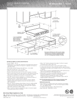
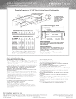
Slide-In Cooktop/Downdraft Vent Countertop Preparation Countertop Preparation for 30" & 36" Slide-In Cooktop / Downdraft Vent Installation 1/4" min. flat ledge E 2 9/16" DC Downdraft vent cutout opening in cooktop support platform 7 1/2" BA For detailed cooktop and 7 1/4" downdraft vent installation specifications, refer to model-specific product page and installation guide on web 1" countertop overhang E30DD75ESS/30" Cooktop Cutout Dimensions Studwall Vertical noncombustible surface - rear wall 1/4" min. flat ledge 2513/16" Downdraft chimney top Countertop* 30" Cooktop A B C D E E30GC74GPS* 29 15/16" 29 3/16" 22" 25 13/16" 27 3/4" 3" 1 15/16" 9/32" Vent unit Slide-In Cooktop E36DD75ESS/36" Cooktop Cutout Dimensions 36" Cooktops A B C D E E36EC75DSS 35 15/16" 35 3/16" 22" 25 13/16" 33 3/4" Stiffener 213/16" End of cooktop support platform Back side of cabinet front E36EC75ESS E36EC75HSS E36GC75DSS* E36GC75ESS* 35 15/16" 35 15/16" 35 15/16" 35 15/16" 35 3/16" 35 3/16" 35 3/16" 35 3/16" 22" 25 13/16" 33 3/4" 22" 25 13/16" 33 3/4" 22" 25 13/16" 33 3/4" 22" 25 13/16" 33 3/4" Cooktop Installation Note: To ensure proper installation, refer to model-specific installation guide on web for cooktop dimensions, cutout dimensions and cabinet requirements. E36GC75GSS* E36GC76EPS* E36GC76GPS* 35 15/16" 35 15/16" 35 15/16" 35 3/16" 35 3/16" 35 3/16" 22" 25 13/16" 33 3/4" 22" 25 13/16" 33 3/4" 22" 25 13/16" 33 3/4" *Proper combination installation will require cooktop power cord to be relocated to underside of unit. (For details, refer to 30" & 36" Gas Slide-In Cooktop Power Cord Relocation Instructions page.) Countertop Preparation Note: Countertop with backsplash may not allow enough flat area for proper installation, 2-13/16" of flat countertop required behind cooktop. No gap required between back of cooktop and front of downdraft trim piece. *Standard 25" countertop depth is NOT adequate for slide-in cooktop / vent installations. Slide-In Cooktop / Downdraft Vent Countertop Preparation Specifications • For detailed Slide-In Cooktop installation, refer to model-specific product page and installation guide on web. Plan installation so that all required minimum clearances between cooktop, overhead cabinets and adjacent vertical walls are provided. • Position cooktop/vent cutout so all required minimum clearances are met. • Minimum flat countertop area must meet or exceed combined overall width and depth as shown. Standard 25" countertop depth is NOT adequate for slide-in cooktop / vent installations. • Separate circuits required for cooktop and vent. (Refer to product-specific electrical specifications.) • Always consult local and national electric and gas codes. Check local building codes for installation requirements, as they may vary per locale. • Proper combination installation will require 30" & 36" Gas Slide-In Cooktop power cord to be relocated to underside of unit. (For details, refer to 30" & 36" Gas Slide-In Cooktop Power Cord Relocation Instructions on web.) Downdraft Vent Specifications • For detailed Downdraft Vent installations, refer to model-specific product page and installation guide on web. • Voltage Rating - 120V / 60 Hz / 15 Amps • Connected Load (kW Rating) @ 120 Volts = 1.0 kW (For use on adequately wired 120V, dedicated circuit having 2-wire service with a separate ground wire. Appliance must be grounded for safe operation.) • Amps @ 120 Volts = 8.0 Amps • Vent unit outside of building only. • Vent must be installed in vertical orientation only. • 1,600 CFM remote exhaust blower (PN # 5304444802) included with vent - shipped in separate box. • Do not use flexible duct. Round duct instead of rectangular duct recommended, especially when elbows are required. • When multiple elbows are necessary, ensure a minimum of 24" of straight duct between any two elbows. • Thermal breaks such as short section of nonmetallic duct, should be used in areas of extreme cold. • For most efficient airflow exhaust, use a straight run or as few elbows as possible. • Cold weather installations should have additional backdraft damper installed. • Installing a Downdraft Vent in combination with any gas cooking surface will affect optimum burner efficiency. • Downdraft Vents can NOT be used in combination with any cooktop backsplash. Note: For planning purposes only. Refer to Product Installation Guide on the web at electroluxicon.com for detailed instructions. Electrolux Major Appliances, N.A. USA • 250 Bobby Jones Expressway • Augusta, GA 30907 • 1-877-4electrolux (1-877-435-3287) • electroluxicon.com CANADA • 5855 Terry Fox Way • Mississauga, ON L5V 3E4 • 1-800-265-8352 • electroluxicon.ca SIC_DDV_PREP 09/09 © 2009 Electrolux Home Products, Inc. High standards of quality at Electrolux Home Products, Inc. mean we are constantly working to improve our products. We reserve the right to change specifications or discontinue models without notice. Printed in the U.S.A.
-
 1
1 -
 2
2 -
 3
3
 |
 |
