Electrolux EDW7505HSS Installation Instructions - Page 1
Electrolux EDW7505HSS - Semi-Integrated Dishwasher With 5 Wash Cycles Manual
 |
UPC - 012505111419
View all Electrolux EDW7505HSS manuals
Add to My Manuals
Save this manual to your list of manuals |
Page 1 highlights
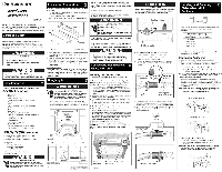
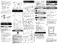
Dishwasher Installation Instructions Printed in U.S.A. 154744001 10/10 INSTALLER: Leave Installation Instructions with owner. OWNER: Read your dishwasher Use and Care Guide. It contains important safety information for operating this appliance. It also has many suggestions for getting the best results from your dishwasher. NOTE: Put unit on its back being careful not to pinch the Water Drain Hose. 1. Remove two (2) screws at front of the kickplate assembly using a #2 Phillips screw driver. 2. Tilt and pull forward to remove see figure 1. NOTE: It is not necessary to remove the outer door for installation. IMPORTANT: For proper operation and appearance of unit, cabinet opening should have dimensions as shown in Figure 2. If unit is to be placed in a corner, there must be at least a 2-inch side clearance to open door. 2. Floor should be flat and free of any obstruction. IMPORTANT: Drain, water, and electrical lines should be roughed-in before going any further. Outer Door Electric Shock Hazard Electrical, water, and drain lines must be confined to shaded areas in Figure 2. Electric conductors, water, and drain could be damaged. Failure to follow these instructions could result in fire or electric shock. Property Damage Do not use the furnished drain hose or a rubber garden hose for the water supply line. Either of these hoses can burst. Flooding may occur and cause property damage. ':::::: DrainH0seC0nnecOt r Read all instructions before installing dishwasher. For your safety, please read and observe all safety instructions. This guide will help you anticipate drain, water, and electrical connections, and help you select the best location for the dishwasher. Top Screws Kickpiat_ Figure 1 Toeplate Kickplate Assembly NOTE: If dishwasher is installed at end of a cabinet, sides and back must be fully enclosed. NOTE: Cabinet Seal Kit (Kit # 154662101). This kit provides a seal between the unit and cabinets once installation is complete. (The Installation Instructions are located in the Kit) 2 k EndStorageLocation Tip Over Hazard Do not use dishwasher until completely installed. Do not push down on open door. Failure to follow this warning can result in serious injury. Cut Hazard To prevent serious injury from sharp edges, wear work gloves when handling, unpacking or disassembling unit. Tools and Materials Needed for Installation (Not Included) • Drill, Electric • Drill Bit 118" • Driver, Socket 8/32",114",8118" • Flaring Tool/Tube Cutter (for copper tubing) • Flashlight • Level • Pipe Joint Compound (for iron pipe plumbing) or Pipe Thread Tape (for sealing threads) • Pliers • Safety Glasses • Saw, Keyhole or Vf, 1 _/2"to 2" Hole Cutters • Screw Drivers, Slotted and #2 Phillips (magnetic tip preferred) • Tape, Electrical or Duct • Tape, Measuring • Wire Stripper or Utility Knife • Wrench, Hex-end • Wrenches, 2 Adjustable (for copper tubing) or 2 Pipe wrenches (for iron pipe plumbing) Parts You Will Need* (Not Included) • Drain Hose Clamp, 1W' Diameter • Brass Elbow, 90 ° with a 3/8"National Pipe Thread • Conduit Connector (UL Listed) • Wire Nuts, three (3) for 12-14 gauge wire (UL Listed) If required: • "Y" Branch Tailpiece and Connector Kit (See Step 4) • Air Gap Kit (See Step 4) All the parts can be found at local hardware, electrical and plumbing supply stores. , Locate water inlet valve behind kickplate on bottom left underside of unit.See Figure 4. The valve has a V?' NPT female fitting. Remove Plug , Wrap 90 ° elbow (not included) with pipe thread tape (or apply joint compound) and thread it into water inlet valve. When tightened, elbow should point toward the left. To prevent bending of bracket or breaking of valve, avoid overtightening. See Figure 4. Weight Keep children away from the front of the dishwasher so that they are not accidentally hit by the door during loading or unloading or if door should unexpectedly open. The weight of the door can cause injury. Cabinet Preparation: As a precaution, it is recommended, but not required that the cabinets enclosing all sides of the dishwasher (including the underside of the countertop) be sealed with an oil based paint or moisture-proof polyurethane to prevent possible steam/ moisture damage. Electric Shock Hazard Observe all local codes and ordinances for electrical and plumbing connections. All electrical and plumbing work should be performed by qualified persons. Failure to follow this warning could result in death or serious injury. , Make sure your location has the correct drain, water, and electrical outlets to make the connections. Do not install unit under a cooktop range. Damage to tub or other components will occur. Electricalwater and draidines must be confined to shadedarea Preferred drain areas Locating the Connections 1. Review dimensions in Figure 2 to locate dishwasher's drain, water, and electrical connections. 2. All utilities must be routed in shaded area in the Figure 2. IMPORTANT: Disconnect power before starting installation. Note: Locate the electrical supply and dishwasher's electrical junction box on right underside of unit behind kickplate assembly. See Figure 4. Determine where you will connect to hot water supply. Review Figure 4 and note the location of water inlet valve. Determine where you will connect the drain hose. 3. Cut access holes for the Electrical, Water and Drain hoses in the shaded areas as shown in Figure 2. 4. The dishwasher operates on a 120 volt, 60 Hz electrical supply. Provide a separate circuit with a fuse or circuit breaker rated for at least 15 amps (20 amps if connected with disposer) but not more than 20 amps. 5. Pull electrical cable through hole into installation area. 6. Be sure water inlet valve is protected from freezing. If valve freezes and ruptures, flooding may occur. 7. Determine amount of tubing needed to connect hot water supply to the unit's water inlet valve. Extra hose length is necessary. High-pressure and high-temperature Stainless Flexible hose with a minimum inner diameter of V4"may be used. A shut-off valve installed outside dishwasher cabinet is best. 8. Route water supply line into installation area. 9. Stand dishwasher back upright for further installation. IMPORTANT: Incoming hot water temperature should be at least 120°F (49°C). Water pressure should be between 20-90 psi. 4%" max. A Figure 2 Front (5/6r"rain. clearance required from unit to 13/4" underside of countertb Left _ 245/8"_ // / ,' Doorin90 ,, openposition NOTE: Pull the hose from "End Storage Location" side. See images below to connect the Drain Hose. L Take drain Hose out of dishwasher and find the end that doesn't have the black rubber material. 2. Use only the spring clamp that is provided in the accessory kit, place spring clamp over one of the hoses. See Image Below. Hose Attached To Dishwasher Remove Plug Plastic End Of Hose Clamp Hose Shipped Inside Dishwasher 3. Take the plastic side of the drain hose and insert it into the hose that is already attached to the dishwasher make sure hose ends are flush against each other. See image below. 4. Secure the spring clamp 1/8" from large end of black hose to the plastic side that was inserted for best sealing results. See Image Below. Plastic Ends of Hoses Flush Hose Attached to Dishwasher , Measure height of cabinet opening from underside of countertop to floor. Check chart for height opening and suggested adjustment. Leg Leveler Adjustment Chart Height of Cabinet Opening Number of Turns to Adjust Levelers 34" (86.4cm) 0 34W' (86.7cm) 2 348h?' (87.2cm) 6 34Vf (87.6cm) 9 2. Move dishwasher to front of installation area. 3. Loosen the rear leveling legs by turning counterclockwise. Refer to chart for number of turns. Dishwasher Anchoring 4. Install the Cabinet Seal Kit (Instructions included in Kit) 5. Choose one of the methods of attachment below to secure unit, holes need to be pre-drilled using a #5 drill bit regardless of the option chosen: a. Side Mount Cabinet Clips (Preferred Method of attachment) b. Top Mount Cabinet Clips (to be used when Side Mount is not an available option) CAUTION: Use extreme care in mounting the dishwasher as to not scratch, bump or otherwise damage the console or tub. To install the Side Mounting Clips. Depending on space allowed in cabinet the Side Mounting Clips can be installed with the holes for the screw up (preferred method) or down as shown in the illustrations below. (Use extreme caution when the clips are in the down position while installing the dishwasher). NOTE: Install Side Mount Brackets before unit is installed into the cabinet. Insert screws into the front holes of the mounting clips only. (See image below) Use if measures 34V8" to 35" screw Use if measures 34" to 34V8" screw To install using Top Mount Cabinet Clips: Depending on the depth of cabinet, the Top Mount Clip have a break off point that can be removed if necessary. NOTE: Install Top Mount Clips before unit is installed into the cabinet. Screw clips firmly to top brace using screws provided in the literature pack. (See image below) k¸ Electric Shock Hazard Disconnect electrical power at the fuse box or circuit breaker box before beginning installation. Failure to follow this warning could result in death or serious injury. *Heightonlyadjustable td N" max.when installedin35tnax4tandard cabine#:utout Figure 3 \ waterinletand powersu_pl_ location(middlebottomrear) S DIMENSIONS DO NOT INCLUDE INSLJ-ATION - INSLJ_ATION BLANKET INSTALLATION. MAY BE COMPRESSED UPON Water Line (Not Included) Figure 4 Brass Elbow (Not Included) Electrical Line Tighten Spring Clamp !I I
-
 1
1 -
 2
2
 |
 |
