Electrolux EFLW427UIW Wiring Diagram English - Page 1

Electrolux EFLW427UIW Manual

Page 1 highlights

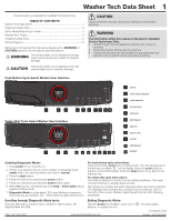
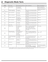
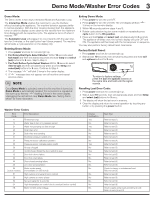
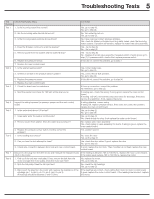
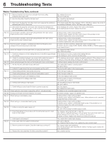
Washer Tech Data Sheet 1 This information is intended for Qualified Technicians Only. TABLE OF CONTENTS Washer Tech Data Sheet 1 Diagnostic Mode Tests 2 Demo Mode/Washer Error Codes 3 Washer Error Codes 4 Troubleshooting Tests 5 Wiring Diagrams 19 Safety items throughout this manual are labeled with a WARNING or CAUTION based on the risk type as described below: WARNING This symbol alerts you to situations that may cause serious body harm, death or property damage. CAUTION This symbol alerts you to situations that may cause bodily injury or property damage. CAUTION Unless otherwise directed, disconnect electrical current before servicing. WARNING The information within this manual is intended for Qualified Service Technicians Only. • DO NOT reach into the appliance while the tub or drum is spinning. • Disconnect power before servicing machine. • Certain internal parts are intentionally not grounded and may present a risk of electric shock only during servicing. Push Button Cycle Select Washer User Interface 1 2 3 4 5 6 7 8 9 10 Rotary Dial Cycle Select Washer User Interface 1 2 3 4 5 6 7 8 11 9 10 1 power 2 cycle status display 3 cycle selector 4 temperature 5 soil level 6 spin speed 7 options 8 select (set) 190 cancel 10 start/pause 11 PODS® Entering Diagnostic Mode: 1 Press power to turn machine on. 2 Rotate cycle selector ring (on some models) or repeatedly press cycles button (on other models) to set cycle to normal. 3 Press the start button. 4 Power off machine by pressing the power button. 5 Power on machine by pressing the power button again. 6 Within 10 seconds, simultaneously hold temp + select (set) buttons together for 3 seconds. 7 Diagnostic Mode is active when LED's start blinking in sequence. This is the pre-test position " ", which tests the lights and buttons. For push button cycle select dryer: Press and hold the cycle button for 2 seconds. The unit will advance to the first test; and flash " " on the display. Press the cycle button to advance to the following test. Press the temp button to go back to the previous test. For rotary dial cycle select dryer: Use knob to advance to the first test by rotating clockwise. Turn knob counterclockwise to navigate previous tests. Test sequence numbers are briefly displayed when each test is selected. The displayed test numbers also correspond to the selector LEDs to the right of the numeric display; beginning with the top LED, following downward. Scrolling through Diagnostic Mode tests: Tests are selected by using the same method to select cycles. See Diagnostic Mode Tests Table. Exiting Diagnostic Mode: Hold the power key for 3 sec, when not in " Buttons, or unplug the unit. USA 1-877-435-3287 www.electroluxappliances.com " test step Lights/ A11200303 (1902) Canada 1-800-265-8352

  • 1
  • 2
  • 3
  • 4
  • 5
  • 6
  • 7
  • 8
  • 9
  • 10
  • 11
  • 12
  • 13
  • 14
  • 15
  • 16
  • 17
  • 18
  • 19
  • 20
  • 21
  • 22
  • 23
  • 24

1
A11200303 (1902)
USA 1-877-435-3287
This information is intended for Qualified Technicians Only.
TABLE OF CONTENTS
Entering Diagnostic Mode:
1 Press
power
to turn machine on.
2 Rotate cycle selector ring (on some models) or repeatedly press
cycles
button (on other models) to set cycle to
normal
.
3 Press the
start
button.
4 Power off machine by pressing the
power
button.
5 Power on machine by pressing the
power
button again.
6 Within
10
seconds, simultaneously hold
temp
+
select (set)
buttons
together for
3
seconds.
7
Diagnostic Mode
is active when LED’s start blinking in sequence.
This is the pre-test position “
”, which tests the lights and buttons.
Safety items throughout this manual are labeled with a
WARNING
or
CAUTION
based on the risk type as described below:
Washer Tech Data Sheet
www.electroluxappliances.com
Canada 1-800-265-8352
Push Button Cycle Select Washer User Interface
Rotary Dial Cycle Select Washer User Interface
This symbol alerts you to situations that may
cause bodily injury or property damage.
This symbol alerts you to situations that may
cause serious body harm, death or property
damage.
CAUTION
WARNING
CAUTION
Unless otherwise directed, disconnect electrical current before
servicing.
Washer Tech Data Sheet
.......................................................................
1
Diagnostic Mode Tests
..........................................................................
2
Demo Mode/Washer Error Codes
..........................................................
3
Washer Error Codes
..............................................................................
4
Troubleshooting Tests
............................................................................
5
Wiring Diagrams
..................................................................................
19
cancel
start/pause
10
7
1
power
2
cycle status display
3
cycle selector
4
temperature
5
soil level
6
spin speed
7
options
8
select (set)
9
2
1
6
3
8
5
4
9
10
2
7
1
6
3
8
5
4
9
10
11
PODS
®
11
WARNING
The information within this manual is intended for Qualified
Service Technicians Only.
DO NOT reach into the appliance while the tub or drum is
spinning.
Disconnect power before servicing machine.
Certain internal parts are intentionally not grounded and may
present a risk of electric shock only during servicing.
Scrolling through Diagnostic Mode tests:
Tests are selected by using the same method to select cycles.
See
Diagnostic Mode Tests Table.
For push button cycle select dryer:
Press and hold the
cycle
button for
2
seconds. The unit will advance to
the first test; and flash “
on the display. Press the
cycle
button to
advance to the following test. Press the
temp
button to go back to the
previous test.
For rotary dial cycle select dryer:
Use knob to advance to the first test by rotating clockwise. Turn knob
counterclockwise to navigate previous tests.
Test sequence numbers are briefly displayed when each test is selected.
The displayed test numbers also correspond to the selector LEDs to
the right of the numeric display; beginning with the top LED, following
downward.
Exiting Diagnostic Mode:
Hold the
power
key for
3
sec, when not in “
” test step Lights/
Buttons, or unplug the unit.