Electrolux EFMG617STT Installation Instructions English Spanish French - Page 13
Electrical connection
 |
View all Electrolux EFMG617STT manuals
Add to My Manuals
Save this manual to your list of manuals |
Page 13 highlights
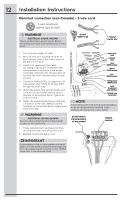
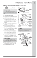
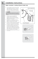
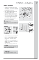
Installation Instructions Electrical connection (non-Canada) - 4 wire cord 4-wire receptacle (NEMA type 14-30R) WARNING ELECTRICAL SHOCK HAZARD Failure to disconnect power source before servicing could result in personal injury or even death. 30 AMP NEMA 14-30 Neutral Ground (WHITE wire) (GREEN wire) 1. Turn off power supply to outlet. 2. Remove the screw securing the terminal block access cover in the lower corner on the back of the dryer. 3. Install a UL-approved strain relief according to the power cord/strain relief manufacturer's instructions in the power cord entry hole below the access panel. At this time, the strain relief should be loosely in place. 4. Thread an UNPLUGGED, UL-approved, 30 amp. power cord, NEMA 14-30 type DRT or SRDT, through the strain relief. 5. Disconnect the internal (WHITE) dryer harness ground wire from the (GREEN) ground screw next to the terminal block. 6. Attach the ground (GREEN) power cord wire to the cabinet with the ground (GREEN) screw. Tighten the screw securely. 7. Move the internal dryer harness ground (WHITE) wire to the terminal block and attach it along with the neutral (WHITE) power cord wire conductor to the center, SILVER colored terminal on the terminal block. Tighten the screw securely. 8. Attach the RED and BLACK power cord conductors to the outer, BRASS colored terminals on the terminal block. Tighten both screws securely. WARNING ELECTRICAL SHOCK HAZARD Do not make a sharp bend or crimp wiring/ conductor at connections. Access cover screw Terminal block Line 2 (BRASS terminal) Neutral (SILVER terminal) Line 1 (BRASS terminal) Internal ground (GREEN screw) Install UL-approved strain relief here Terminal screw recovery slot NOTE If a terminal screw falls during cord installation, it can be retrieved in the terminal screw recovery slot below the access panel. Move internal ground (WHITE) wire to neutral (SILVER) terminal for 4-wire system. Neutral terminal GREEN ground screw WHITE neutral wire 9. Follow manufacturer's guidelines for firmly securing the strain relief and power cord. 10. Reinstall the terminal block cover. GREEN ground wire BLACK or RED power wire BLACK or RED power wire 13
-
 1
1 -
2
-
3
-
4
-
5
-
6
-
7
-
 8
8 -
 9
9 -
 10
10 -
 11
11 -
 12
12 -
 13
13 -
 14
14 -
 15
15 -
 16
16 -
 17
17 -
 18
18 -
19
-
20
-
21
-
22
-
23
-
24
-
25
-
26
-
27
-
28
-
29
-
30
-
31
-
32
-
33
-
34
-
35
-
36
-
37
-
38
-
39
-
40
-
41
-
42
-
43
-
44
-
45
-
46
-
47
-
48
-
49
-
50
-
51
-
52
-
53
-
54
-
55
-
56
-
57
-
58
-
59
-
60
-
61
-
62
-
63
-
64
 |
 |
