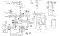
Electrolux EI23BC36IS Wiring Diagram (All Languages) - Page 1
Electrolux EI23BC36IS Manual
 |
UPC - 012505697616
View all Electrolux EI23BC36IS manuals
Add to My Manuals
Save this manual to your list of manuals |
Page 1 highlights
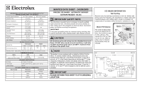
PERFORMANCE DATA NO LOAD & NO DOOR OPENINGS AT 37°/0° CONTROL SETTING (2500++ V4 CONTROLS) Variable Speed Compressor 65°F (18°C) Ambient 90°F (32°C) Ambient Operating Time 32 to 40% 100% Freezer Temperature -6° to 6° F -21° to -14° C -6° to 6° F -21° to -14° C Refrigerator Temperature 33° to 46° F 0.5° to 8° C 33° to 46° F 0.5° to 8° C Low Side Pressure (cut-in) 5 to 12 psig 34 to 83 kPa N/A Low Side Pressure (cut-out) -2 to 2 psig -14 to 14 kPa -2 to 2 psig -14 to 14 kPa High Side Pressure 85 to 95 psig 586 to 655 kPa 120 to 135 psig 827 to 931 kPa Wattage 40 to 55 60 to 70 Amps (running) .5 to 1.1 .7 to .9 Base Voltage 115 vac (127 vac max) DEFROST SPECIFICATIONS Cabinet Size Thermostat Cut-in Cut-out Heater Watts Ohms 23' SD, 28' SD, 23' CD 25° F 47° F 500 26 (-4° C) (8° C) Electronic Timer - (ADC) Defrost 24 minutes every 6-96 hours of compressor run time. CONDENSER FAN MOTOR Watts RPM Amps 3.1 (Energy Star, some models) 1100 CW Opposite Shaft 0.03 Running ICE MAKER SPECIFICATIONS Electrical 115 vac (127 vac max) Thermostat Opens at 48° F (9° C), Closes at 15° F (-9° C) Heater Voltage 85 vac ICE MAKER CONNECTOR PLUG CONNECTIONS Wire Number Wire Color Connects to: 1 Green/Yellow Ground 2 Yellow Water Valve 3 Black Line 4 Light Blue Neutral SERVICE DATA SHEET - 242062500 FREEZER ICE MAKER - AUTOMATIC DEFROST BOTTOM FREEZER - R134a IMPORTANT SAFETY NOTE The information provided herein is designed to assist qualified repair personnel only. Untrained persons should not attempt to make repairs due to the possibility of electrical shock. Disconnect power cord before servicing this appliance. IMPORTANT If any green grounding wires are removed during servicing, they must be returned to their original position and properly secured. CAUTION All electrical parts and wiring must be shielded from torch flame. DO NOT allow torch to touch insulation; it will char at 200°F and flash ignite (burn) at 500°F. Excessive heat will distort the plastic liner. iCE MAKER INFORMATION Test Cycling Remove cover by inserting screwdriver in notch at bottom and prying cover from housing. Use screwdriver to rotate motor gear counterclockwise until holding switch circuit is completed. All components of ice maker should function to complete the cycle. Water Fill Volume The water fill adjustment screw will change the fill time. One full turn is equal to 20cc (.68 oz.). The correct fill is 102 to 130cc (3.4 to 4.3 oz.). When a water valve is replaced, the fill volume must be checked. Water Fill Adjustment Motor Gear Mounting Plate Screw N TUR Mounting Plate Screws Timing Gear NOTE This product comes equipped with an Adaptive Defrost Control (ADC). To activate manual defrost, simultaneously press and hold the Fresh Food up (+) and Fresh Food down (-) keys for 5 seconds. A "d" in the freezer temperature window and "F" in the refrigerator temperature window will display when the heater is activated. To deactivate manual defrost, simultaneously press and hold the Fresh Food up (+) and Fresh Food down (-) keys for 5 seconds. A "d" and "F" will be displayed until the defrost cycle is complete. IMPORTANT PLEASE RETURN THIS SHEET TO IT'S ORIGINAL LOCATION LINE POWER BLK ICE MAKER BLK BRN P-3 THERMAL CUT-OUT ICE MAKER GRN / YEL P-1 MOLD BLK MOTOR HOLD SWITCH NO RED LT. BLUE RED C NC THERMOSTAT NO BLK MOLD HEATER 165 WATTS BLU C NC NO SHUT-OFF SWITCH MOUNTING PLATE C NC YEL ICE MAKER WATER FILL SWITCH GRN / YEL YEL RED YEL ICE MAKER LT. BLUE NEUTRAL P-4 P-2 WATER VALVE
-
 1
1 -
 2
2
 |
 |