Electrolux EI24ID50QS Wiring Diagram (English) - Page 1
Electrolux EI24ID50QS Manual
 |
View all Electrolux EI24ID50QS manuals
Add to My Manuals
Save this manual to your list of manuals |
Page 1 highlights
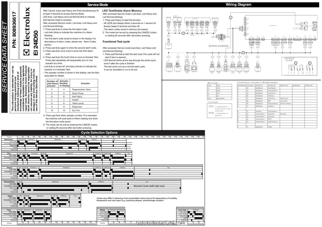
Service Mode Wiring Diagram SERVICE DATA SHEET P/N: 808936617 O ucu O w LT, .o =). 8 $ as .0 o 0 v "a I0C))7Ca3.3•.?E0LtE.4Ee" Z 1.m2ccc23oa.a0ct--.tccsiM oce-l-e.Egces„,i.8C0r-23 .2 2ex1.c55i=aav•0E) 4C-IS Tuceuac->m. o t 3 ma 413 • 63 5 co :ai°€c-EoE2aca.E0)2r0_o.10cv2/c11oo0c4vce1,oiz4EPtocrrmit1•g1oO-ac10ar)3l After Cancel, press pad Heavy and Fast simultaneously for at least 4 seconds to access Service Mode. LED Auto, Led Heavy and Led Normal blink to indicate that Service mode is accesed. After accessed Service mode ( Led Auto, Led Heavy and Led Normal blinking): 1. Press pad Auto to show the first alarm code. - Led Auto blinks to indicate the machine is in Alarm Reading. - The first alarm code saved is shown in the display. For descriptions of alarm codes, please see Alarm Codes section. 2. Press pad Auto again to show the second alarm code. 3. Press pad Auto once more to show the third alarm code. 4. Press pad Auto the fourth time to move to Actuator Test. Press pad repeatedly will sequentially turn on one actuator at a time. - Led Auto is turned off. led Heavy blincks to indicate the machine is in Actuator Test. - The actuator number is shown in the display, see the following table for details. LED Test/Delete Alarm Memory After accessed Service mode ( Led Auto, Led Heavy and Led Normal blinking): 1. Press pad Heavy to start this function. -All LEDS and display blinks 5 seconds on 1 second off. - Buzzer beeps 5 seconds and then off. - The alarm codes saved in memory are erased. 2. The mode can be exit by pressing the CANCEL button, or waiting 60 seconds after last button pressing. Functional Test cycle After accessed Service mode (Led Auto, Led Heavy and Led Normal blinking): 1. Press pad Normal to start the test cycle.The cycle will not start if door is opened. - LED Normal blinks all the way through the whole cycle, even if after the cycle is finished The test cycle runs as a normal wash cycle. It can be cancelled or run to its end. Number of Actuator pad Heavy Number pressed in display Actuator 4 4 Regeneration Valve 5 5 Drain Pump 6 6 Inlet Valve 7 7 Heater 8 8 Wash pump 9 9 Dispenser 10 10 Dry Fan 5. Press pad Auto when actuator number 10 is activated, the machine will cycle back to Alarm reading and show the first alarm code saved. 6. The mode can be exit by pressing the CANCEL button, or waiting 60 seconds after last button pressing. DISPE._NSETR ND 921 INPUT BOARD, 54921 921 54821 4221 PUT BOARD BO 0 IIIII TT B LOW VOLT COORLOCK MAINBOARD °SPENSER INTERFACE I WIRING DIAGRAM Di ° 10 0 BASE BOARD PB100 L 129450) K 129450 J 1294 2 9 H4 5 8 0 1 294 1 2 9. 1 2 9 4 5 8 12 9 C a 129 1 2 21 2 •hoe.21 SOF/. I FAKAr, swoc55 INLET VALVE Ftfi NTOTURB SENSOR PRESSURE SENSOR nn FLOW CONTROL WASH PUMP BLDC PPM PUMP BLDG GROUNDING SCHEME O 0 • 11 Wire-color Code Color bk black br brown bu blue rd red gn/ye green/yellow Line-sty e dotted = Component is currently not in use (reserved) dashed Component is optional Connections included in WireHarnesses WireHamess Connection A 03 A 04 A 05 A 06 A 07 A 08 A 09 A 10 WireEnd 01 BaseBoard BaseBoard BaseBoard BaseBoard BaseBoard BaseBoard BaseBoard BaseBoard WireEnd 02 DoorOpener LeakageSwitch FlowControl InletValve DrainPump BOF PressureSensor Interface I WireEnd 03 WireEnd04 WashPump Lamp (DC) NTC/Turb Sensor B 01 Interface I Userinterface 1 B 02 Userinterface 1 Dispenser RinseAid B 03 Userinterface 1 DoorLock B 04 Userinterface 1 BTFD B 05 Userinterface 1 Userinterface 2 C 01 BaseBoard Heater WireEnd 05 Cycle Selection Options Minutes 5 10 15 20 25 mware PreWash1 PreWash2 Inlet Valve Circulation Pump Drain Pum Heater Dispenser MainWash 601 651 701 751 801 851 901 951 1001 1051 1101 1151 1201 1251 1301 1351 1401 1451 1501 1551 1601 165 iiiiiiiiiiiiiiiiiiiiiiiiiiiiiiiiiiIiiiiIiiiiliiiiliiiiliiiiliiiiliiiiliiiiliiiiliiiiliiiiliiiiliiiiliiiiliiii ColdRinse HotRinse Dry Eco Inlet Valve Circulation Pump Drain Pump Heater Dispenser PW1 PW2 PreWash3 PW4 MainWash ColdRinse1 ColdRinse2 HotRinse ry Heavy Inlet Valve ircu a ion - ump .ram - ump Heater Dispenser PW1 . PW2 . PreWash3 . MainWash ColdRinse1 ColdRinse2 HotRinse Dry M Normal/Auto PW Inlet Valve Circulation Pump Drain Pump Heater Dispenser MainWash HotRinse ry himmaLCa.cleauttiligaLaa Upper Inlet Valve Circulation Pump Drain Pump Heater Dispenser PW1 PW2 MainWash CR HotRinse ry Cycles may differ in behaviour from presentation above due to the dependence of turbidity, temperature and user input. E.g. Less/more phases; shorter/longer duration. Fast PW MainWash 1 MainWash2 HotRinse rose Inlet Valve Inlet Valve Circulation Pump Drain Pump Circ. Pump I II Drain Pum. Heater Heater Dispenser 1111511111 111111112111111 1111 Minutes 10 15 Dispenser 25 30 51 70 lllllllllllllllllllllllllllllllllll IIII Minutes 51 101 15 I I I I I I I I Inlet Valve Drain Pum. Heater Dispenser Minutes IIII 51 11 15
-
 1
1 -
 2
2
 |
 |