Electrolux EI24MO45IB Installation Instructions (All Languages) - Page 2
Basic Specifications - installation
 |
UPC - 012505560576
View all Electrolux EI24MO45IB manuals
Add to My Manuals
Save this manual to your list of manuals |
Page 2 highlights
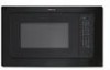
BASIC SPECIFICATIONS MICROWAVE OVEN INSTALLATION INSTRUCTIONS 1. Provide an opening in the wall or cabinet as indicated in Illustration 1. The depth should be a minimum of 20" (50.8 cm). The floor of the opening should be constructed of plywood strong enough to support the weight of the microwave oven (about 100 lbs.) and should be level for proper operation of the oven. NOTE: While the proper functioning of the microwave oven does not require that the opening be enclosed (with sides, ceiling and rear partition), this may be required by local code, and it is suggested that the local code be checked for any such requirement. 2. Outlet should NOT be in the shaded area as indicated on Illustration 1. At the rear of the opening, provide a 3-pronged, polarized, electrical outlet, 115-120 volt AC, 15 amp or larger. 3. Minimum required distance between the microwave oven and the wall oven should be 2-inches of visible cabinet showing after installation. A D G H 6" (15.2 cm) 4" (10.2 cm) B F C E Product overlap 7/8" (2.2 cm) Illustration 1 I J 4" (10.2 cm) installation over an electric wall oven 2" (5.1 cm) minimum gap PRODUCT DIMENSIONS EI30M045T Trim Kit A B C D E 30" (76.2 cm) 18 1/16" (45.9 cm) 2 5/16" (5.9 cm) 24" (60.96 cm) 13 3/8" (33.9 cm) EI27M045T Trim Kit A B C D E 27" (68.6 cm) 18 1/16" (45.9 cm) 2 5/16" (5.9 cm) 24" (60.96 cm) 13 3/8" (33.9 cm) CUTOUT DIMENSIONS min. H max. min. I max. 25 1/4" (64.14 cm) 25 3/8" (64.5 cm) 16 1/4" (41.3 cm) 16 3/8" (41.6 cm) BASIC SPECIFICATIONS OVEN INTERIOR ELECTRICAL REQUIREMENTS Width 17 3/8" (44.1 cm) Height 10 1/2" (26.6 cm) Depth 18 5/8" (47.3 cm) O ver a ll 2.0 cu. ft. 120VAC/60 Hz (UL) 120VAC/60 Hz (CSA) Refer to Illustration 1. All dimensions are in inches (cm). F 17 3/4" (45.1 cm) G min. 30" (76.2 cm) F 17 3/4" (45.1 cm) G min. 27" (68.6 cm) J min. 20" (50.8 cm) Approximate SHIPPING WT. 46 lbs. (20.9 kg) MAX AMP. USAGE 1.5 KW 13.0 amps (UL) 1.50 KW 13 (CSA) E2
-
 1
1 -
 2
2 -
 3
3 -
 4
4 -
 5
5 -
 6
6 -
 7
7 -
 8
8 -
9
-
10
-
11
-
12
 |
 |
