Electrolux EI30DS55LW Installation Instructions (All Languages) - Page 6
Electrical Connection to the, Range U.S.A.
 |
View all Electrolux EI30DS55LW manuals
Add to My Manuals
Save this manual to your list of manuals |
Page 6 highlights
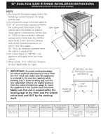
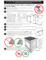
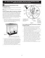
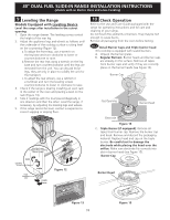
30" DUAL FUEL SLIDE-IN RANGE INSTALLATION INSTRUCTIONS (Models with an Electric Oven and a Gas Cooktop) 3 Electrical Connection to the Range (U.S.A.) This appliance is manufactured with the neutral terminal connected to the frame. Note: Refer to the wiring diagram in the center pages of this manual. Three Conductor Wire Connection to Range (The 3-conductor cord or cable must be replaced with a 4-conductor cord or cable where grounding through the neutral conductor is prohibited in new installations, mobile homes, recreational vehicles or in other areas where local codes do not permit neutral grounding) If local codes permit connection of the frame grounding conductor to the neutral wire of the copper power supply cord (see Figure 3): 1. Remove the 3 screws at the lower end of the rear wire cover, then bend the lower end of the rear wire cover (access cover) upward to expose range terminal connection block (Figure 2). Figure 2 Bend rear wire cover here for access to terminal block 2. Using the nuts supplied in the literature package, connect the neutral white wire of the copper power supply cord to the center silver-colored terminal of the terminal block, and connect the other wires to the outer terminals. Match wires and terminals by color (red wires connected to the right terminal, black wires connected to the left terminal). 3. Lower the terminal cover and replace the 3 screws. Silver colored Terminal Red wire Terminal Block Black wire CMoorudnPtliantge White Wire (Neutral) Grounding Strap A strainrelief supplied by the user must be installed at this location To 240 V receptacle Figure 3 1-1/8" Dia. Direct Connection Hole. Punch out knockout for 1-3/8" Dia. Cord Kit Hole Four Conductor Wire Connection to Range (mobile homes) 1. Remove the 3 screws at the lower end of the rear wire cover, then raise the lower end of the rear wire cover (access cover) upward to expose range terminal connection block (see Figure 2). 2. Remove the grounding strap from the terminal block and from the appliance frame. 3. Using the nuts supplied with the literature package, connect the ground wire (green) of the copper power supply cord to the frame of the appliance with the ground screw, using the hole in the frame where the ground strap was removed (see Figure 4). 4. Connect the neutral of the copper power supply cord to the center silver-colored terminal of the terminal block, and connect the other wires to the outer terminals. Match wires and terminals by color (red wires connected to the right terminal, black wires connected to the left terminal). 5. Lower the terminal cover and replace the 3 screws. 6
-
 1
1 -
 2
2 -
 3
3 -
 4
4 -
 5
5 -
 6
6 -
 7
7 -
 8
8 -
 9
9 -
 10
10 -
 11
11 -
 12
12 -
13
-
14
-
15
-
16
-
17
-
18
-
19
-
20
-
21
-
22
-
23
-
24
-
25
-
26
-
27
-
28
-
29
-
30
-
31
-
32
-
33
-
34
-
35
-
36
-
37
-
38
-
39
-
40
-
41
-
42
-
43
-
44
 |
 |
