Electrolux ELFG7437AG Installation Instructions English - Page 1
Electrolux ELFG7437AG Manual
 |
View all Electrolux ELFG7437AG manuals
Add to My Manuals
Save this manual to your list of manuals |
Page 1 highlights
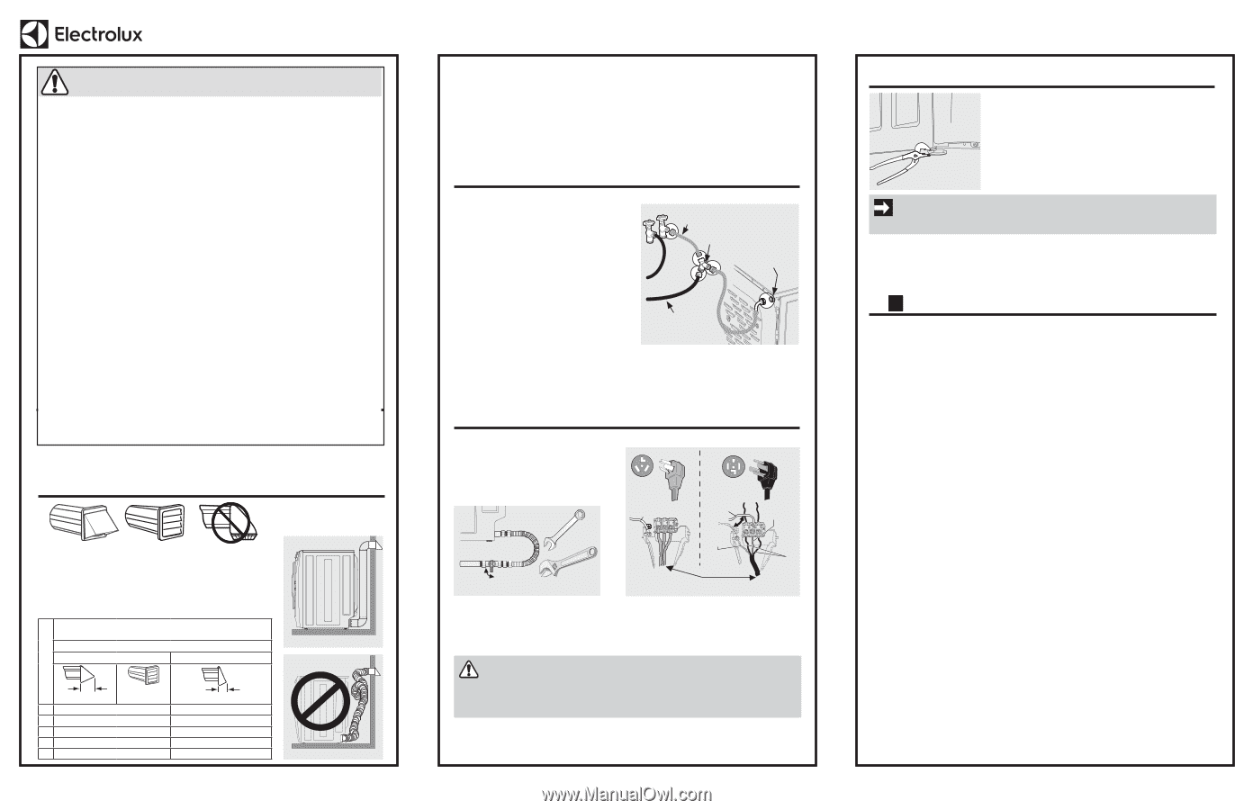
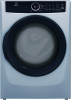
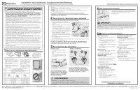
Installation* for Electrolux Front Load Dryer *Please refer to the Use & Care Guide provided with this dryer for further details. TO INSTALLER: Leave these instructions with the customer. WARNING - RISK OF FIRE Read all the following instructions before installing and using this appliance. • Ensure the entire dryer exhaust system is clean and free of lint and debris prior to the installation of your new dryer. The entire exhaust system should be inspected and cleaned a minimum of every 18 months with normal usage. Failure to comply with cleaning your exhaust system will increase the RISK of FIRE. • DO NOT install a clothes dryer with flexible plastic or flexible foil venting material. Flexible venting materials are known to collapse, be easily crushed and trap lint. These conditions will obstruct clothes dryer airflow and increase the risk of fire. • DO NOT screen the exhaust ends of the vent system, or use any screws, rivets or other fasteners that extend into the duct to assemble the exhaust system. NO screen or grate of any mesh size is allowed to cover the outdoor exhaust opening. • Install the clothes dryer according to the manufacturer's instructions and local codes. • Clothes dryer installation and service must be performed by a qualified installer, service agency or the gas supplier. • The electrical service to the dryer must conform with local codes and ordinances and the latest edition of the National Electrical Code, ANSI/NFPA 70, or in Canada, the Canadian Electrical Code CSA C22.1 part 1. • The gas service to the dryer must conform with local codes and ordinances and the latest edition of the National Fuel Gas Code ANSI Z223.1/NFPA 54, or in Canada, the Natural Gas and Propane Installation Code, CSA B149.1. An individual manual shutoff valve must be installed within 6 ft. (1.83 m) of the dryer in accordance with the National Fuel Gas Code, ANSI Z223.1/NFPA 54. • DO NOT stack a dryer on top of washer already installed on pedestal. DO NOT stack washer on top of dryer. DO NOT stack washer on top of another washer. • The dryer is designed under ANSI Z21.5.1/CSA 7.1 or UL 2158 - CAN/CSA C22.2 No. 112 (latest editions) for HOME USE only. This dryer is not recommended for commercial applications such as restaurants, beauty salons, etc. • Destroy the carton and plastic bags after the dryer is unpacked. Children might use them to play. Cartons covered with rugs, bedspreads, or plastic sheets can become airtight chambers causing suffocation. Place all materials in a garbage container or make materials inaccessible to children. • To reduce the risk of severe injury or death, follow all installation instructions in this manual. The instructions in this manual and all other literature included with this dryer are not meant to cover every possible condition and situation that may occur. Good safe practice and caution MUST be applied when installing, operating and maintaining any appliance. 1 Connect or Construct Vent Exhaust NO screen or grate of any mesh size is allowed to cover the exhaust opening. Exhaust system must be vented outside with approved vent hood. • Use only 4 inch rigid or • Use 4" (10.2 cm) clamp to semi-rigid metal ducting. connect dryer & exhaust • Clean lint from duct system. system. • Use only metal foil tape to • Use 90° quick-turn elbow to connect ducts (no screws). vent left or right from dryer. MAXIMUM LENGTH* of 4" (10.2 cm) Rigid Metal Duct VENT HOOD TYPE (Preferred) Correct Number of 90° turns 4" (10.2 cm) louvered 0 125 ft. (38 m) 1 115 ft. (35 m) 2 105 ft. (32 m) 3 95 ft. (29 m) 4 85 ft. (26 m) 2.5" (6.35 cm) 110 ft. (33.5 m) 100 ft. (30.5 m) 90 ft. (27.5 m) 80 ft. (24.5 m) 70 ft. (21.5 m) Incorrect * DO NOT exceed 8 ft. (2.4m) total duct length if installing semi-rigid venting. DO NOT install flexible plastic or flexible foil ducting material. DO NOT use screws, rivets or other fasteners that extend into the duct to assemble the exhaust system. For detailed information, refer to "Exhaust system requirements" and "Clearance requirements" in the Installation sections of the Use & Care Guide provided with this dryer. 2 Connect Water Line (Steam Dryer Only) If this is not a steam dryer, skip to section 3. 1. Inspect all hoses for rubber washers prior to use. 2. Run water from cold outlet to clear contaminants. 3. Connect the dryer Assembly Hose Kit hose extensions from the cold supply to the "Y" connector, then from the "Y" connector to the water inlet on the dryer. 4. Attach the washer cold water supply line to the "Y" connector. Short Hose "Y" Connector Water Inlet on Dryer 5. Tighten all connections by hand, then tighten additional 2/3 turn with pliers. 6. Turn on water and check for leaks. Assembly Hose Kit P/N 5304495002 is not included with purchase of steam model and MUST be purchased separately. Cold Water Supply Hose to Washer For detailed information, refer to "Water connection (Steam Model only)" in the Installation sections of the Use & Care Guide provided with this dryer. 3 Connect to Gas or Electric Gas Dryer 1. Apply approved thread sealant. 2. Wrench-tighten gas line. 3. Open gas valve and check for leaks with soapy water. Electric Dryer 30 AMP 30 AMP Don't Move White Wire Move White Wire White Wire Open Close Manual Shutoff Green Wire Install U.L.-Approved Strain Relief Black or Red Wire For detailed information, refer to "Gas supply requirements" and "Gas connection" in the Installation sections of the Use & Care Guide provided with this dryer. For detailed information, refer to "Electrical system requirements" and "Electrical installation" in the Installation sections of the Use & Care Guide provided with this dryer. WARNING • Dryer must be properly grounded at all times. • LP systems MUST use conversion kit installed by qualified technician. Improper gas installa- tion or LP conversion could result in injury or even death. 4 Level and Connect 1. Use adjustable pliers to adjust the leveling legs so the washer is level front-to-rear and side-to-side, and stable corner-tocorner 2. Connect power. IMPORTANT Please review the "Troubleshooting" section in your Use & Care Guide before calling for service. For detailed information refer to the Installation sections of the Use & Care Guide provided with this dryer. 5 Installation Checklist Exhaust Venting 240v Electric Supply ˆˆ Free-flowing, clear of lint buildup (Electric Dryer) ˆˆ 4 inch (102 mm) rigid metal or semi-rigid metal transition ducting ˆˆ Approved NEMA 10-30 or 14-30 service cord with all screws tight on terminal block of minimal length and turns ˆˆ Approved strain relief installed ˆˆ NO foil or plastic venting material ˆˆ Terminal access cover installed before ˆˆ Approved vent hood exhausted to outdoors initial operation Leveling Door Reversal ˆˆ Dryer is level, side-to-side and front-to-back ˆˆ Follow detailed instructions in this guide ˆˆ Cabinet is sitting solid on all corners ˆˆ Test hinge and latch for function Gas Supply (Gas Dryer) Electrical Power ˆˆ Manual shutoff valve present in supply ˆˆ House power turned on ˆˆ All connections sealed with approved sealer ˆˆ Dryer plugged in and wrench tight Final Checks ˆˆ Conversion kit for LP GAS system ˆˆ Gas supply turned on ˆˆ Door latches and drum tumbles when cycle starts ˆˆ No leaks present at all connections - check ˆˆ Registration card sent in with soapy water, NEVER check with flame Water Hookup (Select Models) ˆˆ Inspect hoses for proper placement of rubber washers ˆˆ Water supply is turned on ˆˆ Check for leaks ˆˆ Steam model dryers require use of ASSEMBLY HOSE KIT #5304495002 (not included) and must be purchased separately SAVE THESE INSTRUCTIONS FOR FUTURE REFERENCE. For support in the U.S. call 1-877-4ELECTROLUX (1-877-435-3287) or visit www.electroluxappliances.com. For support in Canada call 1-800-265-8352 or visit www.electroluxappliances.ca. A17468301 (1907)
-
 1
1 -
 2
2 -
 3
3
 |
 |