Epson 2180 Service Manual - Page 29
EEPROM Control Circuit, Sensor Circuit
 |
UPC - 010343815766
View all Epson 2180 manuals
Add to My Manuals
Save this manual to your list of manuals |
Page 29 highlights
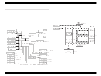
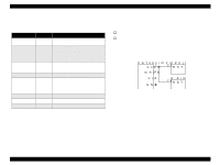
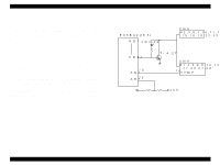
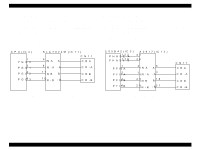
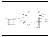
LQ-2180 2.1.6 EEPROM Control Circuit When the printer power is turned off, the EEPROM stores the factory settings and values in the areas that are not cleared in the user setting mode and also writes those values in the RAM. This sequence is managed by the CPU (IC4), which transmits data in the serial format. The EEPROM control circuit is as shown below: Revision A 2.1.7 Sensor Circuit Unlike the LQ-2170, both the CPU and the gate array monitor and control the corresponding sensors' conditions. Note analog voltages are all monitored by the CPU ports. +5V +5V C P U (IC 4 ) P 70 9 P 71 10 P 72 11 P 73 12 A T 9 3 C 4 6 (IC 5 ) 1 CS 2 SK 3 DI 4 DO Figure 2-7. EEPROM Control Circuit +5V R earP E S ensor F ro n t P E S ensor P W ,T O P S ensor +5V C P U (IC 4 ) 70 P 40 76 P 53 68 P 36 75 A N 2 G A (IC 3 ) 61 P 27 IN T 7 1 8 +5V +5V R e le a s e 1 1 1 6 R e le a s e 2 1 1 7 +5V H P S ensor R e le a s e S ensor 2 R e le a s e S ensor 1 P G S ensor C over O pen S ensor Operating Principles Figure 2-8. Sensor Circuit Control Circuit 29
-
 1
1 -
2
-
3
-
4
-
5
-
6
-
7
-
8
-
9
-
10
-
11
-
12
-
13
-
14
-
15
-
16
-
17
-
18
-
19
-
20
-
21
-
22
-
23
-
 24
24 -
 25
25 -
 26
26 -
 27
27 -
 28
28 -
 29
29 -
 30
30 -
 31
31 -
 32
32 -
 33
33 -
 34
34 -
35
-
36
-
37
-
38
-
39
-
40
-
41
-
42
-
43
-
44
-
45
-
46
-
47
-
48
-
49
-
50
-
51
-
52
-
53
-
54
-
55
-
56
 |
 |
