Epson 575W Installation Guide - Page 28
Determine the projection distance and pull out the slider, Route the cables through the wall mount arm
 |
View all Epson 575W manuals
Add to My Manuals
Save this manual to your list of manuals |
Page 28 highlights
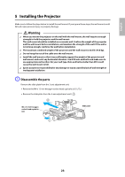
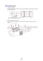
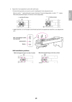
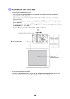
8. Tighten the nut with a wrench to secure the wall plate to the wall. D Determine the projection distance and pull out the slider 1. Using the tables on pages 14 to 21, check the number for the slider measure (b). 2. Loosen the M4 x 12 mm hexagon socket head cap bolts (x2), and then pull out the slider on the wall mount. Align the slider with the measure (b+x) that is equal to the slider measure (b) plus the thickness of the projection screen (x). M4 x 12 mm hexagon socket head cap bolts (x2) Slider measure E Route the cables through the wall mount arm 28
-
 1
1 -
2
-
3
-
4
-
5
-
6
-
7
-
8
-
9
-
10
-
11
-
12
-
13
-
14
-
15
-
16
-
17
-
18
-
19
-
20
-
21
-
22
-
 23
23 -
 24
24 -
 25
25 -
 26
26 -
 27
27 -
 28
28 -
 29
29 -
 30
30 -
 31
31 -
 32
32 -
 33
33 -
34
-
35
-
36
-
37
-
38
-
39
-
40
-
41
-
42
-
43
-
44
-
45
-
46
-
47
-
48
-
49
-
50
-
51
-
52
-
53
-
54
-
55
-
56
-
57
-
58
-
59
-
60
-
61
-
62
-
63
-
64
-
65
-
66
-
67
-
68
-
69
-
70
-
71
-
72
-
73
-
74
-
75
-
76
-
77
-
78
-
79
-
80
-
81
-
82
-
83
-
84
-
85
-
86
-
87
-
88
 |
 |
28
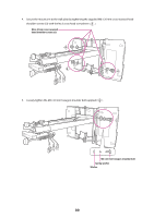
8.
Tighten the nut with a wrench to secure the wall plate to the wall.
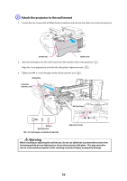
D
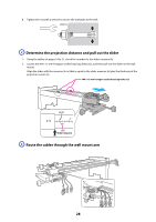
Determine the projection distance and pull out the slider
1.
Using the tables on pages 14 to 21, check the number for the slider measure (b).
2.
Loosen the M4 x 12 mm hexagon socket head cap bolts (x2), and then pull out the slider on the wall
mount.
Align the slider with the measure (b+x) that is equal to the slider measure (b) plus the thickness of the
projection screen (x).
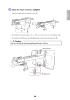
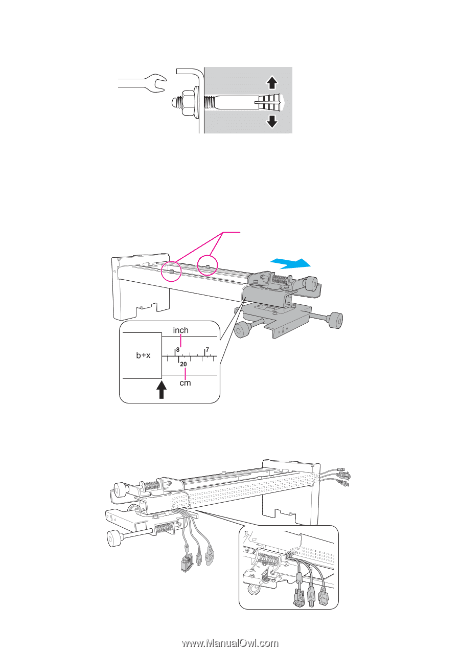
E
Route the cables through the wall mount arm
M4 x 12 mm hexagon socket head cap bolts (x2)
Slider measure