Epson 697Ui Installation Guide - Control Pad and Touch Unit
Epson 697Ui Manual
 |
View all Epson 697Ui manuals
Add to My Manuals
Save this manual to your list of manuals |
Epson 697Ui manual content summary:
- Epson 697Ui | Installation Guide - Control Pad and Touch Unit - Page 1
Touch Unit and Control Pad Guide d'installation de l'unité tactile et du boîtier de commande - Epson 697Ui | Installation Guide - Control Pad and Touch Unit - Page 2
Touch Unit and Control Pad Installation Guide - Epson 697Ui | Installation Guide - Control Pad and Touch Unit - Page 3
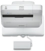
This Installation Guide This guide describes how to mount the Touch Unit and Control Pad for use with your Epson® projector. The following projectors are covered by this guide: • BrightLink® 695Wi/695Wi+/696Ui/697Ui • BrightLink Pro 1450Ui/1460Ui The Control Pad is included with the BrightLink 697Ui - Epson 697Ui | Installation Guide - Control Pad and Touch Unit - Page 4
Unit to BrightLink 695Wi/695Wi+/696Ui/697Ui and BrightLink Pro 1450Wi/1460Ui models only. Do not connect it to any other projectors or Installation Location • The projector must be installed in one of the following locations in order for the Touch Unit to function properly: • Mounted on a wall - Epson 697Ui | Installation Guide - Control Pad and Touch Unit - Page 5
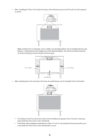
touch unit above the frame of a whiteboard, use the included Touch Unit Bracket. • If the distance from the wall to the surface of the whiteboard is greater than 2 inches (51 mm), you must install the Touch Unit on the whiteboard. • If the frame of the whiteboard extends more than 0.1 inch (3 mm - Epson 697Ui | Installation Guide - Control Pad and Touch Unit - Page 6
31 Adjust the angle 31 Attach labels 39 Attach cover 39 4 Installing the Control Pad (BrightLink 697Ui and 40 BrightLink Pro 1450Ui/1460Ui) Remove the front cover 41 Attach the Control Pad 41 Connect the projector cables to the Control Pad 42 Attach the port protection stickers 42 - Epson 697Ui | Installation Guide - Control Pad and Touch Unit - Page 7
. 11.2 inches [28.5 cm]) (×8) Touch Unit Bracket The following parts are packaged with your projector and are necessary when attaching the Touch Unit above the frame of a whiteboard. When installing the installation plate, you will also need three (3) M4 wood screws or M4 anchor bolts (not included - Epson 697Ui | Installation Guide - Control Pad and Touch Unit - Page 8
3.7 in. (95 mm) English Control Pad (BrightLink 697Ui and BrightLink Pro 1450Ui/1460Ui) The following parts are packaged with your projector and are necessary when attaching the Control Pad. When installing the Control Pad on a wall, you will also need four M4 × 20 mm screws. Control Pad Pen - Epson 697Ui | Installation Guide - Control Pad and Touch Unit - Page 9
Laser diffusion port The laser beam is diffused from the laser diffusion ports on the back of the Touch Unit. Control Pad External dimensions and weight The Control Pad weighs approximately 8.2 ounces (262 g). 5.4 in (135.9 mm) 0.4 in (11.5 mm) 4.4 in (111 mm) 4.3 in (109 mm) 0.1 in (3.5 mm) - Epson 697Ui | Installation Guide - Control Pad and Touch Unit - Page 10
English Cable routing holes When routing cables through a wall, use the position ( ) in the following figure as the cable routing hole. Otherwise, remove the cable cover ( ) and route the cables through the opening. Route - Epson 697Ui | Installation Guide - Control Pad and Touch Unit - Page 11
than 0.1 inch (3 mm) away from the board surface, you must install the Touch Unit on the whiteboard. Caution The Touch Unit should only be connected to the BrightLink 695Wi/695Wi+/696Ui/697Ui or BrightLink Pro 1450Ui/1460Ui models. Do not connect the Touch Unit to any other projectors or devices. 10 - Epson 697Ui | Installation Guide - Control Pad and Touch Unit - Page 12
menus may differ slightly from the illustrations, but the installation instructions are the same. Install the Touch Unit Bracket on a flat, smooth, unwarped projector Remote Control Control Panel B Display the installation pattern 1. Press the Menu button on the remote control or the projector - Epson 697Ui | Installation Guide - Control Pad and Touch Unit - Page 13
4. Select Installation Pattern. The Installation pattern is displayed on the projected image. C Remove the dial cover 1. Loosen the screw at the bottom of the dial cover. 2. Slide the dial cover down to remove it. 12 - Epson 697Ui | Installation Guide - Control Pad and Touch Unit - Page 14
position for the Touch Unit Bracket Mark the following installation positions: • ( ): The center line of the installation pattern; align it with the center line of the installation plate ( ). • ( ): 1 to 4 inches (25 to 100 mm) from the top edge of the projected image; align with the bottom - Epson 697Ui | Installation Guide - Control Pad and Touch Unit - Page 15
the Touch Unit Bracket 1. Secure the installation plate on the wall using three (3) M4 wood screws or anchor bolts (not included). 2. Attach the Touch Unit to the securing plate with the M4 × 25 mm hexagon socket - Epson 697Ui | Installation Guide - Control Pad and Touch Unit - Page 16
securing plate with the supplied hexagon wrench. 4. Measure the distance from the wall to the surface of the whiteboard (f ). ❏ If the distance from the wall to the surface of the whiteboard is greater than 2 inches (51 mm), you must install the Touch Unit on the whiteboard. ❏ If the frame of the - Epson 697Ui | Installation Guide - Control Pad and Touch Unit - Page 17
hexagon socket head cap bolt into Touch Unit and tighten the bolt until the Touch Unit is parallel to the installation plate. The bolt used varies based on the distance from the wall to the surface of the whiteboard (f ) that you measured in step 4. If (f ) is 0.8 to 1.4 inches (20 to 35 mm - Epson 697Ui | Installation Guide - Control Pad and Touch Unit - Page 18
interactive pen(s) before adjusting the angle. Press the User button on the remote control and select Yes to perform an auto-calibration. Refer to the projector's User's Guide for detailed instructions on calibrating the pen(s). 1. Select Easy Interactive Function from the Extended menu. 17 - Epson 697Ui | Installation Guide - Control Pad and Touch Unit - Page 19
Setup. 3. Select Power and set to On. The Touch Unit power turns on and the indicator light turns blue. Warning Do not look into the projector's projection window or the Touch Unit's laser diffusion ports (located on the back of the Touch Unit); this could cause injury to eyesight. When Power - Epson 697Ui | Installation Guide - Control Pad and Touch Unit - Page 20
English 5. Select Installing the Touch Unit with the bracket. The Angle Adjustment screen is displayed. 6. Tighten the adjustment screw on the Touch Unit one turn with the included - Epson 697Ui | Installation Guide - Control Pad and Touch Unit - Page 21
8. Attach the two markers to the positions shown on the projected screen ( ) ( ). Blue marker position Green marker position Match the positions so that the crosses ( ) overlap with the points ( ) on the marker positions ( ) ( ). Move the marker over the projected cross until the lines of the - Epson 697Ui | Installation Guide - Control Pad and Touch Unit - Page 22
English 9. Loosen the adjustment screw until the circles appear on the screen. Loosen or tighten the adjustment screw so that the pointers move inside of the target ( ) ( ) of the same color (blue and green) on either side. Loosening the adjustment screw moves the pointers diagonally up towards the - Epson 697Ui | Installation Guide - Control Pad and Touch Unit - Page 23
10. When the circles on the left and right become solid ( ), press the button on the remote control. The following screen is displayed: 11. Turn the adjustment dials on the Touch Unit to move the circles so that they move inside of the target ( ) ( ) of the same color (blue and green) on either side - Epson 697Ui | Installation Guide - Control Pad and Touch Unit - Page 24
English Turning an adjustment dial counterclockwise moves the pointer diagonally down away from the center of the projected image. When the pointers are inside the target, the circles become solid ( ). ❏ If a dial makes a clicking sound, the pointer will not move any further. ❏ When turning the - Epson 697Ui | Installation Guide - Control Pad and Touch Unit - Page 25
13. Place the markers at the top marker positions [1]. When angle adjustment is performed correctly, the upper circles become solid ( ). If the upper circles do not become solid ( ), start again from step 4. 14. Place the markers at the bottom marker positions [2]. When angle adjustment is performed - Epson 697Ui | Installation Guide - Control Pad and Touch Unit - Page 26
the or button on the remote control and repeat step 12. • If the dots still remain after removing obstacles, select Additional Adjustments and follow the instructions. • If the dots still remain or there are obstacles that cannot be removed, such as whiteboard trays or frames, go to step 17. 25 - Epson 697Ui | Installation Guide - Control Pad and Touch Unit - Page 27
do not disappear even after attaching the infrared deflectors, select Additional Adjustments and follow the instructions. If the dots do not disappear even after performing the above procedures, contact Epson. 18. Perform touch calibration by pressing Menu on the remote control. On the Extended - Epson 697Ui | Installation Guide - Control Pad and Touch Unit - Page 28
but the installation instructions are the same. ❏ There are magnets built in to the back of the Touch Unit. Typically, the Touch Unit should be installed by projector Remote Control Control Panel B Display the installation pattern 1. Press the Menu button on the remote control or the projector - Epson 697Ui | Installation Guide - Control Pad and Touch Unit - Page 29
3. Select Touch Unit Setup. 4. Select Installation Pattern. The Installation pattern is displayed on the projected image. C Remove the dial cover 1. Loosen the screw at the bottom of the dial cover. 28 - Epson 697Ui | Installation Guide - Control Pad and Touch Unit - Page 30
English 2. Slide the dial cover down to remove it. D Determine the installation position for the Touch Unit Mark the following installation positions: • ( ): The center line of the installation pattern; align it with the center line of the Touch Unit 1 to 4 inches (25 to 100 mm) from the top edge - Epson 697Ui | Installation Guide - Control Pad and Touch Unit - Page 31
Touch Unit on a magnetic surface, be careful not to trap your fingers or any other part of your body between the magnets and the installation surface. • For non-magnetic boards or screens, attach the spacers to the screw holes on the back of the Touch Unit Secure the Touch Unit - Epson 697Ui | Installation Guide - Control Pad and Touch Unit - Page 32
interactive pen(s) before adjusting the angle. Press the User button on the remote control and select Yes to perform an auto-calibration. Refer to the projector's User's Guide for detailed instructions on calibrating the pen(s). 1. Select Easy Interactive Function from the Extended menu. 31 - Epson 697Ui | Installation Guide - Control Pad and Touch Unit - Page 33
Setup. 3. Select Power and set to On. The Touch Unit power turns on and the indicator light turns blue. Warning Do not look into the projector's projection window or the Touch Unit's laser diffusion ports (located on the back of the Touch Unit); this could cause injury to eyesight. When Power - Epson 697Ui | Installation Guide - Control Pad and Touch Unit - Page 34
English 5. Select Installing the Touch Unit without the bracket. The Angle Adjustment screen is displayed. 6. Turn the adjustment dials on the Touch Unit counterclockwise until you hear a click. - Epson 697Ui | Installation Guide - Control Pad and Touch Unit - Page 35
7. Attach the two markers to the positions shown on the projected screen ( ) ( ). Blue marker position Green marker position Match the positions so that the crosses ( ) overlap with the points ( ) on the marker positions ( ) ( ). Move the marker over the projected cross until the lines of the - Epson 697Ui | Installation Guide - Control Pad and Touch Unit - Page 36
English 8. Turn the adjustment dials on the Touch Unit to move the circles ( ) so that they move inside of the target ( ) ( ) of the same color (blue and green) on either side. Turning an adjustment dial clockwise moves the pointer diagonally up towards the center of the projected image. Turning an - Epson 697Ui | Installation Guide - Control Pad and Touch Unit - Page 37
9. When the circles on the left and right become solid( ), press the button on the remote control. The following screen is displayed: 10. Place the markers at the top marker positions [1]. When angle adjustment is performed correctly, the upper circles become solid ( ). If the upper circles do not - Epson 697Ui | Installation Guide - Control Pad and Touch Unit - Page 38
English 12. When you have finished checking the marker positions, remove the markers and press the button on the remote control. The following confirmation screen is displayed: 13. Trace the dots with your finger as shown. When angle adjustment is performed correctly, the traced dots disappear. - Epson 697Ui | Installation Guide - Control Pad and Touch Unit - Page 39
do not disappear even after attaching the infrared deflectors, select Additional Adjustments and follow the instructions. If the dots do not disappear even after performing the above procedures, contact Epson. 15. Perform touch calibration by pressing Menu on the remote control. On the Extended - Epson 697Ui | Installation Guide - Control Pad and Touch Unit - Page 40
English H Attach labels Attach the labels to the tabs on either side of the Touch Unit. Match the centers of the labels with the tabs on the Touch Unit. If the Touch Unit moves out of position, use the position of the labels to determine where to reposition the Touch Unit. I Attach cover Attach the - Epson 697Ui | Installation Guide - Control Pad and Touch Unit - Page 41
697Ui and BrightLink Pro 1450Ui/1460Ui) You must install the projector before installing the Control Pad. Follow the steps below to install the Control Pad and connect to the projector. Caution The Control Pad should only be connected to the BrightLink 697Ui and BrightLink Pro 1450Ui/ 1460Ui. Do not - Epson 697Ui | Installation Guide - Control Pad and Touch Unit - Page 42
English If you are using the Touch Unit, make sure that you do not install the Control Pad or Pen Stand in the shaded areas of the following figure. The Touch Unit will not operate correctly if anything is obstructing - Epson 697Ui | Installation Guide - Control Pad and Touch Unit - Page 43
use the Control Pad. To perform the functions listed below, you will need to connect the appropriate cables: Projector function Required cables Supplying power from the projector Stereo mini connection cable (included) Projecting images from a USB flash drive Saving data to a USB flash drive - Epson 697Ui | Installation Guide - Control Pad and Touch Unit - Page 44
English E Attach the front cover 43 - Epson 697Ui | Installation Guide - Control Pad and Touch Unit - Page 45
to install a driver that enables pen or finger touch interactivity to work. Both software programs are included with the BrightLink or BrightLink Pro projector. For details, see the online User's Guide or visit: U.S.: epson.com/support/brightlinkdownloads Canada: epson.ca/support/brightlinkdownloads - Epson 697Ui | Installation Guide - Control Pad and Touch Unit - Page 46
Guide d'installation de l'unité tactile et du boîtier de commande - Epson 697Ui | Installation Guide - Control Pad and Touch Unit - Page 47
ce guide d'installation Le présent guide décrit la façon d'installer l'unité tactile et le boîtier de commande pour l'utilisation avec votre projecteur Epson®. Ce guide fournit des explications pour les projecteurs suivants : • BrightLink® 695Wi/695Wi+/696Ui/697Ui • BrightLink Pro 1450Ui/1460Ui Le - Epson 697Ui | Installation Guide - Control Pad and Touch Unit - Page 48
connectez l'unité tactile qu'aux modèles BrightLink 695Wi/695Wi+/696Ui/697Ui et BrightLink Pro 1450Wi/1460Ui. Ne la connectez pas à d'autres projecteurs mauvais fonctionnement des appareils ou supports. Emplacement pour l'installation • Le projecteur doit être installé dans l'un des emplacements - Epson 697Ui | Installation Guide - Control Pad and Touch Unit - Page 49
• La surface est plate, lisse et régulière avec moins de 5 mm (0,2 po) d'inégalité (dans toutes les directions) sur la surface de l'écran. 5 mm (0,2 po) • Si vous installez l'unité tactile à l'intérieur du cadre d'un tableau blanc, fixez-la à l'aide d'aimants ou de vis. Assurez-vous qu'il n'y a pas - Epson 697Ui | Installation Guide - Control Pad and Touch Unit - Page 50
vous installez l'unité tactile au-dessus du cadre d'un tableau blanc, utilisez le support de l'unité tactile inclus. • Si la distance entre le mur et la surface du tableau blanc est supérieure à 51 mm (2 po), vous devez installer l'unité tactile sur le tableau blanc. • Si le cadre du tableau blanc - Epson 697Ui | Installation Guide - Control Pad and Touch Unit - Page 51
installation 56 Retirez le couvercle des cadrans 57 Déterminez la position d'installation du support de l'unité tactile 58 Installez le support Fixez le couvercle 84 4 Installation du boîtier de commande (BrightLink 697Ui 85 et BrightLink Pro 1450Ui/1460Ui) Retirez le couvercle avant 86 - Epson 697Ui | Installation Guide - Control Pad and Touch Unit - Page 52
po]) pour fixer les marqueurs (×12) Déflecteurs infrarouges (environ 28,5 cm [11,2 po]) (×8) Support de l'unité tactile Les pièces suivantes sont emballées avec votre projecteur et sont nécessaires lors de l'installation de l'unité tactile au-dessus du cadre d'un tableau blanc. Lorsque vous fixez - Epson 697Ui | Installation Guide - Control Pad and Touch Unit - Page 53
Boîtier de commande (BrightLink 697Ui et BrightLink Pro 1450Ui/1460Ui) Les pièces suivantes sont emballées avec votre projecteur et sont nécessaires lors de l'installation du boîtier de commande. Lorsque vous installez le boîtier de commande sur un mur, vous aurez aussi besoin de quatre vis M4 x 20 - Epson 697Ui | Installation Guide - Control Pad and Touch Unit - Page 54
Français Ports de diffusion du laser Le faisceau laser est émis depuis les ports de diffusion laser à l'arrière de l'unité tactile. Boîtier de commande Dimensions externes et poids Le boîtier de commande pèse environ 262 g (9,2 oz). 135,9 mm (5,4 po) 11,5 mm (0,4 po) 111 mm (4,4 po) 109 mm - Epson 697Ui | Installation Guide - Control Pad and Touch Unit - Page 55
Trous pour le passage des câbles Lorsque vous faites passer les câbles à travers un mur, utilisez la position ( ) dans l'illustration suivante comme trou pour le passage des câbles. Sinon, retirez le cache-câbles ( ) et faites passer les câbles à travers l'ouverture. Faites passer le câble de l' - Epson 697Ui | Installation Guide - Control Pad and Touch Unit - Page 56
+/696Ui/697Ui ou BrightLink Pro 1450Ui/1460Ui. Ne branchez pas l'unité tactile à d'autres projecteurs ou appareils. Installation de l'unité tactile au-dessus d'un tableau blanc Suivez les étapes ci-dessous pour installer l'unité tactile au-dessus d'un tableau blanc à l'aide du support de l'unit - Epson 697Ui | Installation Guide - Control Pad and Touch Unit - Page 57
motif d'installation 1. Appuyez sur le bouton Menu de la télécommande ou du panneau de commande du projecteur. Télécommande Panneau de configuration 2. Sélectionnez Easy Interactive Function depuis le menu Avancé. 3. Sélectionnez Config. uni. tactile. 4. Sélectionnez Motif d'installation. 56 - Epson 697Ui | Installation Guide - Control Pad and Touch Unit - Page 58
Français Le motif d'installation s'affiche sur l'image projetée. C Retirez le couvercle des cadrans 1. Desserrez la vis dans la partie inférieure du couvercle des cadrans. 2. Faites glisser le couvercle des cadrans afin de le retirer. 57 - Epson 697Ui | Installation Guide - Control Pad and Touch Unit - Page 59
projetée. Alignez avec le bord inférieur de la plaque d'installation. 25 à 100 mm (1 à 4 po) L'unité tactile doit être installée au-dessus de la zone d'image. E Installez le support de l'unité tactile 1. Fixez la plaque d'installation au mur à l'aide de trois (3) vis à bois ou boulons d'ancrage - Epson 697Ui | Installation Guide - Control Pad and Touch Unit - Page 60
boulons avec la clé à six pans fournie. Mise en garde Lors de l'installation de l'unité tactile sur la plaque de fixation, veillez à ne pas de fixation. 3. Fixez l'unité tactile et la plaque de fixation à la plaque d'installation à l'aide des boulons à tête cylindrique à six pans M4 × 12 mm (×2) - Epson 697Ui | Installation Guide - Control Pad and Touch Unit - Page 61
tableau blanc est de plus de 3 mm (0,1 po) d'épaisseur, vous devez installer l'unité tactile sur le tableau blanc. 5. Desserrez les deux boulons à tê l'unité tactile. Alignez les flèches sur la gauche et la droite du support de l'unité tactile selon la distance (f) mesurée à l'étape 4. Lorsque vous - Epson 697Ui | Installation Guide - Control Pad and Touch Unit - Page 62
à six pans M4 × 55 mm ou M4 × 70 mm dans l'unité tactile et serrezle jusqu'à ce que l'unité tactile soit parallèle avec la plaque d'installation. Le type de boulon utilisé dépend de la distance entre le mur et la surface du tableau blanc (f ) mesurée à l'étape 4. Si (f ) mesure entre 20 et - Epson 697Ui | Installation Guide - Control Pad and Touch Unit - Page 63
bouton User de la télécommande et sélectionnez Oui afin d'effectuer un calibrage automatique. Veuillez consulter le Guide de l'utilisateur en ligne pour obtenir des instructions détaillées sur le calibrage des crayons. 1. Sélectionnez Easy Interactive Function depuis le menu Avancé. 2. Sélectionnez - Epson 697Ui | Installation Guide - Control Pad and Touch Unit - Page 64
Français 3. Sélectionnez Alimentation et réglez le paramètre à On. L'unité tactile s'allume et le témoin indicateur s'allume en bleu. Avertissement Ne regardez pas la fenêtre de projection du projecteur ou les ports de diffusion laser de l'unité tactile. Ceci pourrait entraîner des problèmes - Epson 697Ui | Installation Guide - Control Pad and Touch Unit - Page 65
5. Sélectionnez Installation de l'unité tactile avec le support. L'écran de réglage de l'angle s'affiche. 6. Serrez la vis d'ajustement sur l'unité tactile (un seul tour) avec la clé à six pans fournie. 7. Tournez les deux - Epson 697Ui | Installation Guide - Control Pad and Touch Unit - Page 66
8. Fixez les deux marqueurs aux positions indiquées sur l'écran projeté ( ) ( ). Français Position du marqueur bleu Position du marqueur vert Faites correspondre les positions de sorte que les croix ( ) soient superposées avec les points ( ) sur les positions des marqueurs ( ) ( ). Déplacez le - Epson 697Ui | Installation Guide - Control Pad and Touch Unit - Page 67
9. Desserrez la vis d'ajustement jusqu'à ce que les cercles apparaissent à l'écran. Desserrez ou serrez la vis d'ajustement de manière à ce que les marqueurs se déplacent au centre de la cible ( ) ( ) de même couleur (bleu et vert) sur chaque côté. Lorsque vous desserrez la vis d'ajustement, le - Epson 697Ui | Installation Guide - Control Pad and Touch Unit - Page 68
Français 10. Lorsque les cercles à gauche et à droite deviennent unis ( ), appuyez sur le bouton de la télécommande. L'écran suivant s'affiche : 11. Tournez les cadrans d'ajustement de l'unité tactile pour déplacer les cercles de sorte qu'ils se retrouvent dans la cible ( ) ( ) de même couleur ( - Epson 697Ui | Installation Guide - Control Pad and Touch Unit - Page 69
Lorsque vous tournez un cadran d'ajustement dans le sens contraire des aiguilles d'une montre, le pointeur se déplace à la diagonale vers le bas en direction opposée du centre de l'image projetée. Lorsque les pointeurs sont dans la cible, les cercles deviennent unis ( ). ❏ Si vous entendez un clic - Epson 697Ui | Installation Guide - Control Pad and Touch Unit - Page 70
Français 13. Placez les marqueurs sur les positions de marqueur supérieures [1]. Si le réglage de l'angle a été effectué correctement, les cercles supérieurs deviennent unis ( ). Si les cercles supérieurs ne deviennent pas unis ( ), retournez à l'étape 4. 14. Placez les marqueurs sur les positions - Epson 697Ui | Installation Guide - Control Pad and Touch Unit - Page 71
commande et répétez l'étape 12. • Si les points sont toujours là après avoir retiré tous les obstacles, sélectionnez Réglages suppl. et suivez les instructions qui s'affichent. • Si les points ne disparaissent pas ou si certains obstacles ne peuvent être enlevés, tels que des plateaux pour tableau - Epson 697Ui | Installation Guide - Control Pad and Touch Unit - Page 72
pas après avoir effectué les procédures ci-dessus, communiquez avec Epson. 18. Effectuez le calibrage tactile en appuyant sur la touche Menu , puis Config. uni. tactile. Sélectionnez Calibrage tactile et suivez les instructions qui s'affichent. H Posez le couvercle Fixez le couvercle des cadrans. - Epson 697Ui | Installation Guide - Control Pad and Touch Unit - Page 73
é tactile sur un tableau blanc Suivez les étapes ci-dessous pour installer l'unité tactile sur un tableau blanc. Il est possible que l'apparence de certains menus soit différente des illustrations, mais les instructions d'installation demeurent les mêmes. ❏ Des aimants sont intégrés à l'arrière de - Epson 697Ui | Installation Guide - Control Pad and Touch Unit - Page 74
Français 3. Sélectionnez Config. uni. tactile. 4. Sélectionnez Motif d'installation. Le motif d'installation s'affiche sur l'image projetée. C Retirez le couvercle des cadrans 1. Desserrez la vis dans la partie inférieure du couvercle des cadrans. 73 - Epson 697Ui | Installation Guide - Control Pad and Touch Unit - Page 75
Faites glisser le couvercle des cadrans afin de le retirer. D Déterminez la position d'installation de l'unité tactile Veuillez marquer les positions d'installation suivantes : • ( ) : Ligne centrale du motif d'installation. Alignez-la avec la ligne centrale de l'unité tactile 25 à 100 mm (1 à 4 po - Epson 697Ui | Installation Guide - Control Pad and Touch Unit - Page 76
é tactile sur une surface magnétique, veillez à ne pas coincer vos doigts ou toute autre partie de votre corps entre les aimants et la surface d'installation. • Pour les tableaux et écrans non magnétiques, fixez les séparateurs sur les trous de vis à l'arrière de l'unité tactile. Puis, fixez l'unit - Epson 697Ui | Installation Guide - Control Pad and Touch Unit - Page 77
sur le bouton User de la télécommande et sélectionnez Oui afin d'effectuer un calibrage automatique. Veuillez consulter le Guide de l'utilisateur en ligne pour obtenir des instructions détaillées sur le calibrage des crayons. 1. Sélectionnez Easy Interactive Function depuis le menu Avancé. 76 - Epson 697Ui | Installation Guide - Control Pad and Touch Unit - Page 78
Français 2. Sélectionnez Config. uni. tactile. 3. Sélectionnez Alimentation et réglez le paramètre à On. L'unité tactile s'allume et le témoin indicateur s'allume en bleu. Avertissement Ne regardez pas la fenêtre de projection du projecteur ou les ports de diffusion laser de l'unité tactile (situés - Epson 697Ui | Installation Guide - Control Pad and Touch Unit - Page 79
5. Sélectionnez Installation de l'unité tactile sans le support. L'écran de réglage de l'angle s'affiche. 6. Tournez les cadrans de réglage de l'unité tactile dans le sens inverse des aiguilles d'une montre jusqu'à ce que - Epson 697Ui | Installation Guide - Control Pad and Touch Unit - Page 80
7. Fixez les deux marqueurs aux positions indiquées sur l'écran projeté ( ) ( ). Français Position du marqueur bleu Position du marqueur vert Faites correspondre les positions de sorte que les croix ( ) soient superposées avec les points ( ) sur les positions des marqueurs ( ) ( ). Déplacez le - Epson 697Ui | Installation Guide - Control Pad and Touch Unit - Page 81
8. Tournez les cadrans d'ajustement de l'unité tactile pour déplacer les cercles ( ) de sorte qu'ils se retrouvent dans la cible ( ) ( ) de même couleur (bleu et vert) de chaque côté. Lorsque vous tournez un cadran d'ajustement dans le sens des aiguilles d'une montre, le pointeur se déplace à la - Epson 697Ui | Installation Guide - Control Pad and Touch Unit - Page 82
Français 9. Lorsque les cercles à gauche et à droite deviennent unis ( ), appuyez sur le bouton de la télécommande. L'écran suivant s'affiche : 10. Placez les marqueurs sur les positions de marqueur supérieures [1]. Si le réglage de l'angle a été effectué correctement, les cercles supérieurs - Epson 697Ui | Installation Guide - Control Pad and Touch Unit - Page 83
12. Lorsque vous avez terminé la vérification des positions des marqueurs, retirez les marqueurs et appuyez sur le bouton de la télécommande. L'écran de confirmation suivant s'affiche : 13. Tracez les points avec votre doigt tel qu'illustré. Si le réglage de l'angle est effectué correctement, les - Epson 697Ui | Installation Guide - Control Pad and Touch Unit - Page 84
retiré tous les obstacles, sélectionnez Réglages suppl. et suivez les instructions qui s'affichent. • Si les points ne disparaissent pas ou si les déflecteurs infrarouges, sélectionnez Réglages suppl. et suivez les instructions qui s'affichent. Si les points ne disparaissent toujours pas apr - Epson 697Ui | Installation Guide - Control Pad and Touch Unit - Page 85
. uni. tactile. Sélectionnez Calibrage tactile et suivez les instructions qui s'affichent. H Collage des étiquettes Apposez les étiquettes tactile se déplace hors position, utilisez les étiquettes pour déterminer où réinstaller l'unité tactile. I Fixez le couvercle Fixez le couvercle des cadrans. - Epson 697Ui | Installation Guide - Control Pad and Touch Unit - Page 86
Le boîtier de commande ne doit être connecté qu'aux modèles BrightLink 697Ui et BrightLink Pro 1450Ui/1460Ui. Ne connectez pas le boîtier de commande à d'autres modèles de projecteur. Vérifiez l'emplacement pour l'installation Assurez-vous qu'il y a assez d'espace autour du boîtier de commande pour - Epson 697Ui | Installation Guide - Control Pad and Touch Unit - Page 87
Si vous utilisez l'unité tactile, assurez-vous de ne pas installer le boîtier de commande ou le porte-crayon dans les zones ombrées de l'illustration suivante. L'unité tactile ne fonctionnera pas correctement si le - Epson 697Ui | Installation Guide - Control Pad and Touch Unit - Page 88
Français Vérifiez si le boîtier de commande fonctionne correctement avant de le fixer avec les vis. C Connectez les câbles du projecteur au boîtier de commande Câble USB 1 Câble USB 2 Mini câble de connexion stéréo Câble USB 5 Câble USB 3 Câble USB 4 Clé USB Vous devez brancher le mini câ - Epson 697Ui | Installation Guide - Control Pad and Touch Unit - Page 89
les projecteurs BrightLink ou BrightLink Pro. Pour obtenir plus de détails, consultez le Guide de l'utilisateur en ligne ou le site Web à l'adresse suivante : www.epson.ca/support/brightlinklogiciels Fixation d'un câble de sécurité Utilisez la fente de sécurité sur votre projecteur pour installer un - Epson 697Ui | Installation Guide - Control Pad and Touch Unit - Page 90
CPD-50949 Printed in XXXXXX Pays d'impression : XXXXXX
-
 1
1 -
 2
2 -
 3
3 -
 4
4 -
 5
5 -
 6
6 -
 7
7 -
8
-
9
-
10
-
11
-
12
-
13
-
14
-
15
-
16
-
17
-
18
-
19
-
20
-
21
-
22
-
23
-
24
-
25
-
26
-
27
-
28
-
29
-
30
-
31
-
32
-
33
-
34
-
35
-
36
-
37
-
38
-
39
-
40
-
41
-
42
-
43
-
44
-
45
-
46
-
47
-
48
-
49
-
50
-
51
-
52
-
53
-
54
-
55
-
56
-
57
-
58
-
59
-
60
-
61
-
62
-
63
-
64
-
65
-
66
-
67
-
68
-
69
-
70
-
71
-
72
-
73
-
74
-
75
-
76
-
77
-
78
-
79
-
80
-
81
-
82
-
83
-
84
-
85
-
86
-
87
-
88
-
89
-
90
 |
 |
Touch Unit and Control Pad
Guide d’installation de l’unité tactile et
du boîtier de commande