Epson 697Ui Installation Guide - Control Pad and Touch Unit - Page 25
If the bottom circles do not become solid
 |
View all Epson 697Ui manuals
Add to My Manuals
Save this manual to your list of manuals |
Page 25 highlights
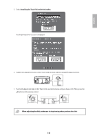
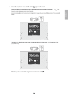
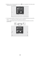
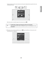
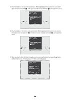
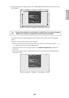
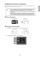
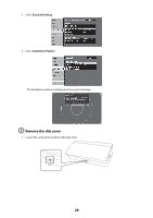
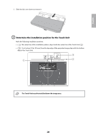
13. Place the markers at the top marker positions [1]. When angle adjustment is performed correctly, the upper circles become solid ( ). If the upper circles do not become solid ( ), start again from step 4. 14. Place the markers at the bottom marker positions [2]. When angle adjustment is performed correctly, the bottom circles become solid ( ). If the bottom circles do not become solid ( ), start again from step 4. 15. When you have finished checking the marker positions, remove the markers and press the button on the remote control. The following confirmation screen is displayed: 24
-
 1
1 -
2
-
3
-
4
-
5
-
6
-
7
-
8
-
9
-
10
-
11
-
12
-
13
-
14
-
15
-
16
-
17
-
18
-
19
-
 20
20 -
 21
21 -
 22
22 -
 23
23 -
 24
24 -
 25
25 -
 26
26 -
 27
27 -
 28
28 -
 29
29 -
 30
30 -
31
-
32
-
33
-
34
-
35
-
36
-
37
-
38
-
39
-
40
-
41
-
42
-
43
-
44
-
45
-
46
-
47
-
48
-
49
-
50
-
51
-
52
-
53
-
54
-
55
-
56
-
57
-
58
-
59
-
60
-
61
-
62
-
63
-
64
-
65
-
66
-
67
-
68
-
69
-
70
-
71
-
72
-
73
-
74
-
75
-
76
-
77
-
78
-
79
-
80
-
81
-
82
-
83
-
84
-
85
-
86
-
87
-
88
-
89
-
90
 |
 |
24
13.
Place the markers at the top marker positions [1]. When angle adjustment is performed correctly, the
upper circles become solid (
). If the upper circles do not become solid (
), start again from step 4.
14.
Place the markers at the bottom marker positions [2]. When angle adjustment is performed correctly,
the bottom circles become solid (
). If the bottom circles do not become solid (
), start again from
step 4.
15.
When you have finished checking the marker positions, remove the markers and press the
button
on the remote control. The following confirmation screen is displayed: