Epson ActionNote 4SLC/25 Product Information Guide - Page 4
Major Subassemblies, Connector Pin Assignments, Serial Port Connectors J1 and J6
 |
View all Epson ActionNote 4SLC/25 manuals
Add to My Manuals
Save this manual to your list of manuals |
Page 4 highlights
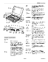
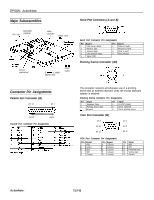
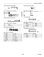
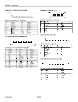
EPSON ActionNote Major Subassemblies Serial Port Connectors (J1 and J6) CPU chip \ fax/modem (optional) \ / numeric coprocessor video controller I Dallas clock Serial Port Connector Pin Assignments Pin I Signal I Pin I Signal I 1 Data carrier detect 6 Data set ready 2 Receive data 7 Request to send 3 Transmit data 8 Clear to send 4 Data terminal ready 9 Ring indicator 5 Signal GND Pointing Device Connector (J10) \ 3 l&inch, 1.44MB diskette drive power supply Connector Pin Assignments Parallel Port Connector (J2) pin 13 pin 1 I I l oooooooooo~ I pin 25 I pin 14 Parallel Port Connector Pin Assignments This connector supports simultaneous use of a pointing device and an external keyboard when the mouse/keyboard adapter is attached. Pointing Device Connector Pin Assignments Pin 1 2 13 1 Signal Keyboard Data Pointing device data Ground Pin Signal 4 +5 VDC (fused) 5 Clock, keyboard 1 6 1 Clock, pointing device I VGA Port Connector (J3) pin 5 pin 1 pin 10 pin 15 pin 6 pin 11 VGA Port Connector Pin Assignments Pin Signal 1 Red 2 Green 3 Blue 4 MS2 5 Ground Pin Signal 6 Ground 7 Ground a Ground 9 Unused 10 Ground Pin Signal 11 MS0 12 MS1 13 Horizontal sync 14 Vertical sync 15 Unused ActionNote- 7/27/93
-
 1
1 -
 2
2 -
 3
3 -
 4
4 -
 5
5 -
 6
6 -
 7
7
 |
 |
