Epson B113111 Installation Guide - Page 22
Peel off the Velcro tapes, and, shown in illustration 60.
 |
View all Epson B113111 manuals
Add to My Manuals
Save this manual to your list of manuals |
Page 22 highlights
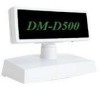
English 3. Pass the cable for the DM-D500 through the hole on fixing plate A, and fix the cable at the bottom as 58 shown in illustration 58. 4. Connect the cable for the DM-D500 to the DC connector on the TM printer as shown in illustration 59. 59 5. Store any excess cable in the support, and attach the DM-D500 to fixing plate A as 60 shown in illustration 60. 6. Peel off the Velcro tapes, and attach the display to the setting position. Assembling using screws 1. Follow steps 2 and 3 in "Assembling using Velcro tapes." 2. Secure fixing plate A to the setting 61 position with fixing screws as shown in illustration 61. 3. Attach the DM-D500 to fixing plate A. 20 DM-D500 Installation Guide
-
 1
1 -
2
-
3
-
4
-
5
-
6
-
7
-
8
-
9
-
10
-
11
-
12
-
13
-
14
-
15
-
16
-
 17
17 -
 18
18 -
 19
19 -
 20
20 -
 21
21 -
 22
22 -
 23
23 -
 24
24 -
 25
25 -
 26
26 -
 27
27 -
28
-
29
-
30
-
31
-
32
-
33
-
34
-
35
-
36
-
37
 |
 |

20
DM-D500 Installation Guide
English
3.
Pass the cable for the
DM-D500 through the hole
on fixing plate A, and fix
the cable at the bottom as
shown in illustration 58.
4.
Connect the cable for the DM-D500 to the DC connector on the
TM printer as shown in illustration 59.
5.
Store any excess cable in the
support, and attach the
DM-D500 to fixing plate A as
shown in illustration 60.
6.
Peel off the Velcro tapes, and
attach the display to the setting
position.
Assembling using screws
1.
Follow steps 2 and 3 in “Assembling
using Velcro tapes.”
2.
Secure fixing plate A to the setting
position with fixing screws as shown in
illustration 61.
3.
Attach the DM-D500 to fixing plate A.
58
59
60
61