Epson B134101 Installation Manual - Page 17
Attaching to the TM-H6000/TM-U675
 |
View all Epson B134101 manuals
Add to My Manuals
Save this manual to your list of manuals |
Page 17 highlights
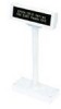
6. Store any excess cable in the support, and attach the DM-D210 to fixing plate A. English Attaching to the TM-H6000/TM-U675 The DM-D210 can be attached directly to the TM-H6000/TM-U675 printers using the "DM-D pole unit for TM printers (Type A)" (DP-502). You can attach fixing plate A on either side of the TM-H6000/TM-U675. After attaching it, you can slide the display freely. Required items The following items are used to attach the DM-D210 to the TM-H6000/ TM-U675 printers. These items are packed with the "DM-D pole unit for TM printers (Type A)" (DP-502). stopper fixing screw angle fixing for stopper screw fixing screws for rubber feet (small) rubber feet (small) fixing plate B fixing screws for fixing plate B support C support B for extension fixing plate A 15
-
 1
1 -
2
-
3
-
4
-
5
-
6
-
7
-
8
-
9
-
10
-
11
-
 12
12 -
 13
13 -
 14
14 -
 15
15 -
 16
16 -
 17
17 -
 18
18 -
 19
19 -
 20
20 -
 21
21 -
 22
22 -
23
-
24
-
25
-
26
-
27
-
28
-
29
-
30
-
31
-
32
-
33
-
34
-
35
-
36
-
37
-
38
-
39
-
40
-
41
-
42
 |
 |
