Epson ES-600C Product Information Guide - Page 3
DIP SWITCHES, PIN ASSIGNMENTS, Parallel, SCSI, Scanners, ES-600C-3
 |
View all Epson ES-600C manuals
Add to My Manuals
Save this manual to your list of manuals |
Page 3 highlights
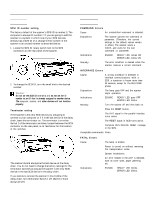
Dip Switches microseconds at the ~1 Default setting: All Off Pin Assignments Parallel Signal pin assignments Pin Return Signal No. pin Direction 1 19 STROBE STROBE pulse to read in or send out data. Pulse width must be more than 0.5 microseconds at the receiving terminal. 2 20 DATA0 IN/OUT These signals represent 3 21 DATA1 IN/OUT information of bits 1 to 8, 4 22 DATA2 IN/OUT respectively. Each signal is at a 5 23 DATA3 IN/OUT high level when data is logical 1 6 24 DATA4 IN/OUT and low when it is logical 0. 7 25 DATA5 IN/OUT 8 26 DATA6 IN/OUT 9 27 DATA7 IN/OUT 10 28 ACKNLG OUT/(IN) About a 12-microsecond pulse. Low indicates that data has been received and that the scanner is ready to accept more data. 11 29 BUSY OUT/(IN) When this signal is high, the scanner cannot receive data. The signal is high: 1) during data entry 2) during scanning 3) when the scanner is not ready 4) when the scanner has an error 0 Regarding Pin No. 19-30. "return" denotes the twisted-pair return, to be connected at signal ground level. For interface wiring, be sure to use a twisted-pair cable for each signal, and to complete the connection on the return side. These cables should be shielded and the ground connected to the chassis of the host computer and the scanner. 0 All interface conditions are based on TTL level. SCSI Signal pin assignments Scanners 11/2/92 ES-600C-3
-
 1
1 -
 2
2 -
 3
3 -
 4
4 -
 5
5
 |
 |
