Epson Ensemble HD 720 Schematic - Page 2
Audio Input Connector (DB15), Sub Woofer Output Connector (RCA Style) - area code
 |
View all Epson Ensemble HD 720 manuals
Add to My Manuals
Save this manual to your list of manuals |
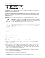
Page 2 highlights
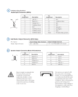
A Interface Specifications Audio Input Connector (DB15) Pin Assignment Description 5 15 1 2 3 4 5 1 6 6 6 7 8 Left Ch + Right Ch + Center Ch + Common Gnd N/C Common Gnd Common Gnd Common Gnd Pin Assignment 9 10 11 12 13 14 15 Shell Description N/C Common Gnd N/C N/C Surr Left + Surr Right + Sub + Chassis safety ground B Sub Woofer Output Connector (RCA Style) Pin: Signal Shield: Signal Ground Input Voltage (Sub Channel) Output Voltage (Sub Out) .85 - 1.25V rms 1.7V - 2.5V rms (6dB Gain Circuit) C Speaker Output Connector (Molex 10-Conductor) 2 1 10 9 Pin Assignment 1 2 3 4 5 Description Right Ch + Right Ch Center Ch + Center Ch Surr R + Pin Assignment 6 7 8 9 10 Description Surr RSurr L+ Surr LLeft Ch + Left Ch - Epson strongly recommends that ! the home theatre system be installed by a professional audio/video installer or other qualified professional. Epson cannot provide advice concerning construction practices or building codes in your area. Two persons are required to lift the screen onto its mounting brackets. It is recommended that a second person should also assist in performing other parts of the installation, such as mounting the projector and routing wires. Personal injury and/or damage to the equipment could result from dropping or mishandling it.
-
 1
1 -
 2
2 -
 3
3 -
 4
4 -
 5
5 -
 6
6 -
 7
7 -
 8
8 -
9
 |
 |
